Keyswitch options, Remote signalling equipment (auto-dialler), Figure 1: auto dialler connections – Noby UK Noby-65 User Manual
Page 6
Noby-65 Installation Manual & Operating Instructions (Rev.1)
Page 6 of 12
KEYSWITCH OPTIONS
Internal Keyswitch
The Noby-65 has an internal keyswitch fitted as standard, supplied with 4 keys. The switch has the following
positions:
i) OFF:
All Intruder circuits are disarmed. Other 24-hour circuits remain active.
ii) FULL-SET:
All Intruder circuits are armed. Noby-65 is Full-Set after the Exit Time.
iii) PART-SET:
Noby-65 is Part-Set after the Exit Time, with Zone-2 isolated.
External Keyswitch Connections [B14,B15,B16,B17]
The Noby-65 can be operated remotely by connecting an external keyswitch to terminals B15-B17 as shown in
Figure 3. Note that switching terminal B15 to 0v causes the Noby-65 to Full-Set, whilst switching terminal B17 to
0v causes the Noby-65 to Part-Set. Terminal B16 is the 0v connection. Terminals B14 and B15 must be linked
together for correct operation of the internal keyswitch.
An attractive alternative to a mechanical keyswitch is the Nobycode NC-02 Remote Keypad (Figure 4). The NC-
02 is specifically designed to control the Full-Set, Part-Set and System Reset functions of the Noby-65. The NC-02
keypad also has 2 LEDs to remotely indicate the ON/OFF status and the Alarm/Fault status of the Noby-65.
For additional security it is recommended to remove the two EOL resistors from the Noby-65 terminals and re-
connect them in the remote keyswitch housing, such that any break in the cable will force the Noby-65 to either
Full-Set or Part-Set the intruder system.
For high security installations it is also recommended to route the Sabotage circuit though the cable and connect
through any lid microswitches.
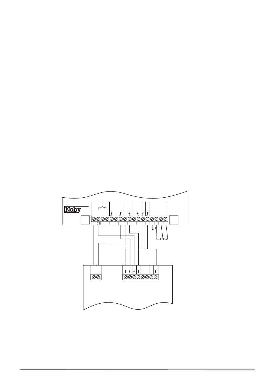
REMOTE SIGNALLING EQUIPMENT (AUTO-DIALLER)
The Noby-65 cabinet can accomodate an Auto-Dialler underneath the main circuit board assembly. Figure 1
shows a typical Auto-Dialler connection diagram. The channel numbers may differ according to the signal priorities
demanded by the remote central station. Also take care to ensure that the Water Alarm channel is programmed to
be a negative going input signal.
B
B
Power
Alarm Channels
1 2 3 4 5 6 7 8
0v
12v
Remote Signalling Equipment
(Auto-Dialler)
65
External
Keyswitch
Connection
01
03 04 05 06 07
09
08
10 11
14
12 13
16
15
17
In
tr
u
d
er
Sir
en
24hr
12hr
Wa
te
r
Buzzer
Panic
SW+
Full
Part
0V
12V
0V
0V
NO
C
NC
12V
Fire
Figure 1: Auto Dialler Connections