System leds - interpretation – Noby UK Noby-220iR2 2-Zone User Manual
Page 23
Noby-220iiiiR2 Installation Manual
Page 23
Software Revision1-0
-
-
-
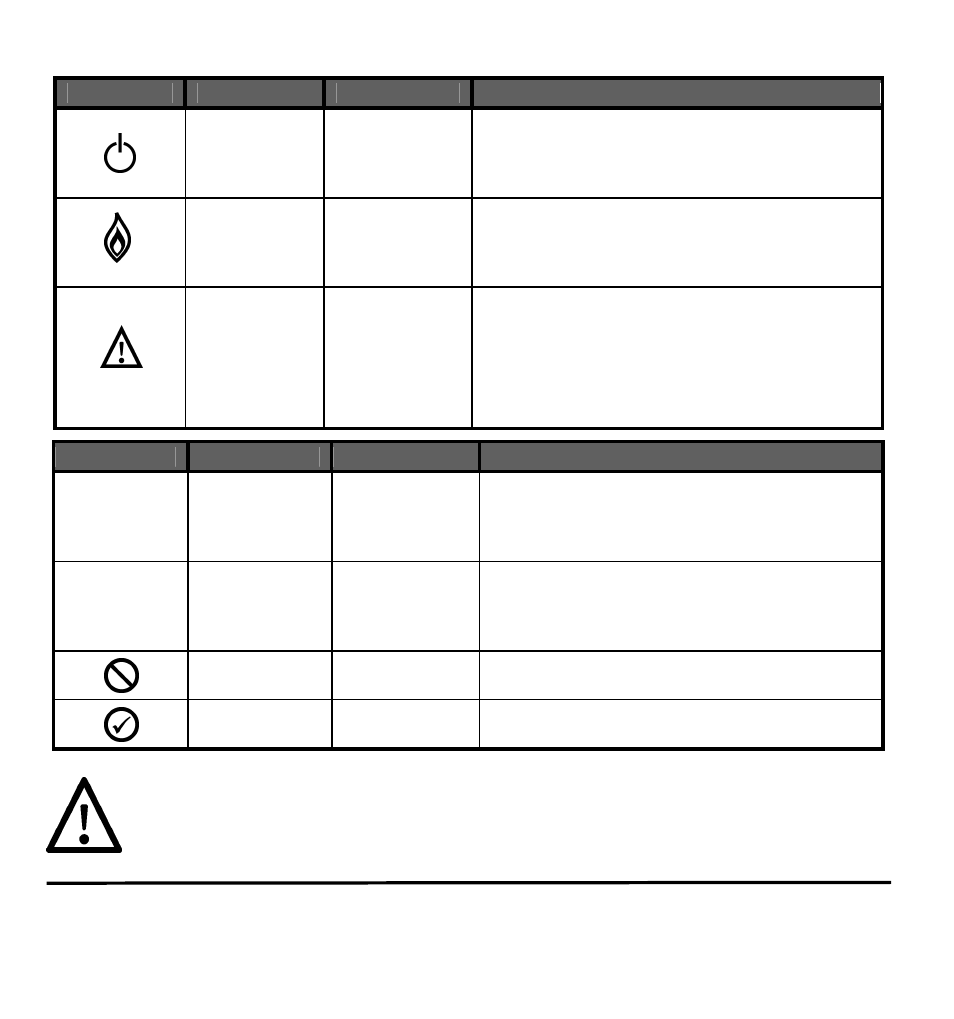
System LEDs - Interpretation
LED Label
Description
Status
Interpretation
Power
(green)
a) steady on
b) off
c) 1 blink / 4s
d) rapid flash
230VAC Mains OK
230VAC Mains Loss
230VAC Mains Restored (memory)
Code entered - awaiting a command key
Common Fire
(red)
a) steady on
b) pulsing
Local fire on Zone-1 or Zone-2
Fire alarm signalled from a remote panel
(the pulse count indicates the address no)
Common
Fault
(yellow)
a) steady on
b) 1 flash / 4s
c) 2 flash / 4s
All local panel zone & sounder circuit faults, Fault
I/P, remote panel and iiiinterlink bus faults.
Accompanied by one or more secondary fault
LEDs which identify the specific fault condition.
230VAC Mains Loss
Battery Low Voltage (pending Final Voltage)
LED Label
Description
Status
Interpretation
PSU
PSU Fault
(yellow)
a) 1 flash / 4s
b) 2 flash / 4s
c) 3 flash / 4s
d) 4 flash / 4s
230VAC Mains Loss (real time status)
PSU Low Volts (latched memory)
PSU Charger Fault
Battery O/C, Fuse F3 or Battery Ri-max fault
CPU
CPU Fault
(yellow)
a) steady on
b) 1 flash / 4s
c) 2 flash / 4s
d) 3 flash / 4s
CPU Fault (loss of comms to display PCB)
CPU Watchdog occurred (restarted OK)
Programme Memory Checksum Error
EEPROM Data Memory Checksum Error
Disablement
(yellow)
steady on
All or part of the system is disabled
Test
(yellow)
steady on
Test Mode
Latched fault conditions are cleared by performing a Panel Reset. A persistent
reoccurring fault condition could indicate a pending loss of functionality, which
should be investigated by a competent person at the earliest. If in any doubt
contact the installation company.