Kaman DIT-5200L User Manual
Page 4
______________________________________________________________________________
Kaman Precision Products
PART NO: 860522-001
www.kamansensors.com
Last Revised 11/16/2012
- 4 -
PART 2 – CONNECTING THE DIT-5200L
2.1 What’s Included
DIT-5200L Signal Conditioning Electronics
2 or 4 sensors (Typically 15N or 20N)
18” Input/Output Cable
2.2 Cautions and Safeguards
The sensor faces may be damaged if allowed to strike the target or other hard surface. Protective
plastic caps should remain in place until the sensors are ready for installation.
The maximum input voltage to the DIT-5200L is +/-15.5V, exceeding this input voltage will cause
damage to the DIT-5200L.
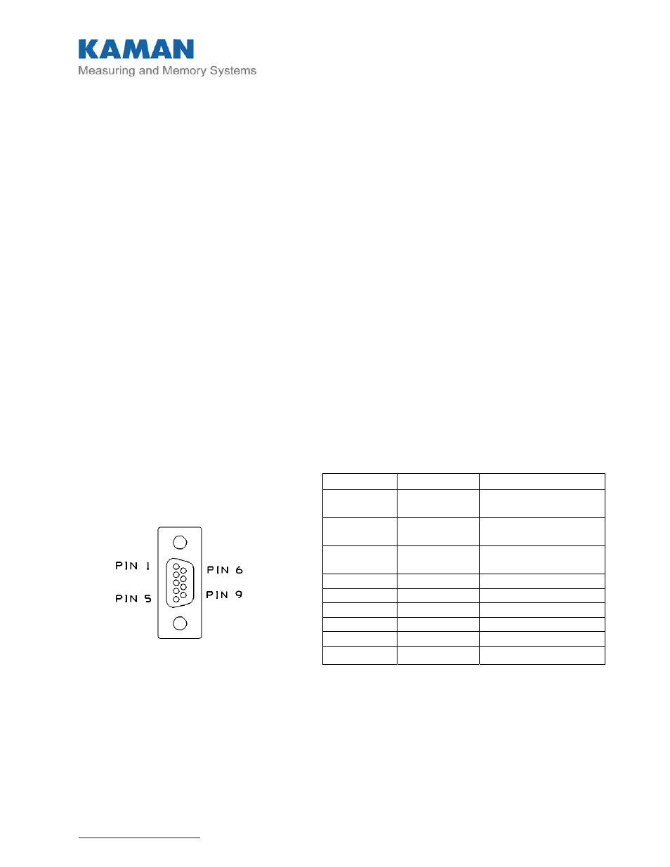
2.3 Pin out and Connector Assignments
The DIT-5200L I/O connections are via an ITT Cannon model MDM-9SL2P connector on the
enclosure. A mating connector with 18 inch leads is provided as part of the system. Connection
information is detailed below.
Figure 2 I/O Connector
Sensor connections are the same for both the enclosure style and the OEM DIT-5200L. On the
OEM DIT-5200L orient the box so the I/O connector is on the right and the sensor connections
are on the left.
Pin Color Function
1
Black
+15V @ 40 mA
(typical).
2
Brown
-15V @ 40 mA
(typical)
3 Red
Power
Supply
Common
4 Orange +X
Output
5 Yellow -X
(Gnd)
6 Green +Y
Output
7 Blue -Y(Gnd)
8 Violet
N/C
9 Gray
N/C