0 wiring installation, Proseries, 1 electrical connections – Blue-White Sonic-Pro S4 Ultrasonic Flowmeters User Manual
Page 6: Sonic-pro, T1 t2 t3 t4, Sonic-pro 4.4 wiring terminals
Transducer A
Transducer B
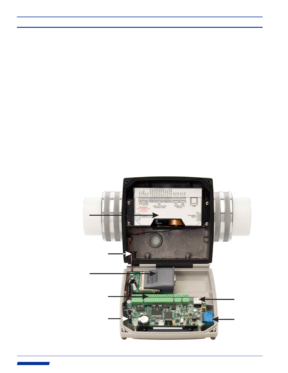
The meter must be powered by 15 to 28 volts DC. Depending on the model ordered, an
AC/DC plug-in transformer may have been be supplied for this purpose. See the diagram
below for wiring of output signals, communications signals and process control relays.
The transducer cable length is factory fixed. Do not attempt to modify the length of these
cables. Various cable lengths are available from the factory. Contact the factory if you need
assistance.
Shielded cable is recommended for signal output connections.
4.1
Electrical
Connections
Page 5
Sonic-Pro
The Sonic-Pro SPU wiring compartment is equipped with:
Ÿ
Three liquid-tight cable gland connectors for cable diameter from .200 to .394 inches (5.1
to 10.0 mm).
Ÿ
Two liquid-tight cable gland connectors cable for diameters from .118 to .255 inches (3.0 to
6.5 mm).
Ÿ
One communications cable liquid-tight cable gland grommet for cable diameters from .190
to .205 inches. It is provided for any one of the following cable types:
Ethernet Cable
RS-232 serial cable
Note that the blank grommet plug should be used when the communications cable grommet
is not required.
4.2
Cable Gland
Liquid-Tight
Connections
4.3
Wiring
Compartment
4.0 Wiring Installation
Back-up
Battery
Compartment
(4 D cells -
not included)
Optional
Communications
Circuitry
Wiring Terminals
Main PCB
USB
Connection
Touchpad
Connection
Communications
Circuitry
Input Socket
Communications
Cable Grommet
TRANSDUCER
INPUTS
POWER
INPUTS
USER INTERFACE
CONNECTIONS
USB
TOUCHPAD
INPUT
ANYBUS
COMMUNICATIONS
WARNING
INPUT POWER LIMITS
DC INPUT
15~28 Vdc-15W
RED (+)
BLK (-)
GRN
RED (+)
BLK (-)
GRN
Transducer A
DC (-)
Chassis
DC PWR
DC (+)
V Bat (+)
Battery
V Bat (-)
Pulse In (-)
Relay
A
(n/o)
Pulse In (+)
Relay A
Pulse Out (+)
Pulse
Pulse Out (-)
Relay
A
(n/c)
Relay
A
(com)
Relay B (n/o)
Relay B (n/c)
Relay B (com)
Analog Out (+)
4-20 mA
Analog Out (-)
Relay B
Paddle
Transducer B
T1
T2
T3
T4
5
4
3
2
1
10 9 8 7
6 5 4 3
2 1
3
2
1
3
2
1
13 12 11
Chassis
Page 6
Sonic-Pro
4.4
Wiring
Terminals
FUNCTION
TERM PIN #
DESCRIPTION
POWER INPUT:
Primary power
T1
1
2
RATING
(+) 15-28 Vdc
(-) 15-28 Vdc
Chassis Ground
T1
3
Ground
POWER INPUT:
Battery Back-up power
T1
4
5
(+) Positive
(-) Negative
15-28Vdc, 400mA max
4 D cell size batteries
(Alkaline batteries only are acceptable)
PULSE FREQUENCY
OUTPUT:
Open Collector
T2
1
2
(+) Positive
(-) Negative
Type: Open collector w/ internal 1 K pull-up to 5V.
Can be pulled up to 30V @ 10mA (3K pull-up)
Duty Cycle: 50%+/-5%
Frequency Range: 0-1000 Hz
Resolution: 1 Hz
Accuracy: 0.5% F.S.
PADDLEWHEEL
SENSOR INPUT:
AC Sine wave
T2
3
4
(+) Positive
(-) Negative
Blue-White model FC sensor.
100mVp-p, 10 to 350Hz
RELAY ‘A’ OUTPUT
T2
5
6
Normally Open
Common
Type: FORM C
Load capacity: 30V, 100mA max (ext. supplied)
7
Normally Closed
RELAY ‘B’ OUTPUT
T2
8
9
Normally Open
Common
Type: FORM C
Load capacity: 30V, 100mA max (ext. supplied)
10
Normally Closed
ANALOG OUTPUT:
4-20 mA
T2
12
13
(+) Positive
(-) Negative
Current output: 4-20 mADC, isolated.
Max Load Impedance: 1K ohm
Power: Internal
Resolution: 12 bits
Accuracy: Less than 0.1% F.S.
Update Rate: 1.0 s
The terminal blocks are plug type capable of accepting 14 to 30 AWG wire.
TRANSDUCER
INPUT:
Transducer A
T3
1
2
(+) Red
(-) Black
3
Green or Bare
TRANSDUCER
INPUT:
Transducer B
T4
1
2
(+) Red
(-) Black
3
Green or Bare
Chassis Ground
T2
11
Ground
Industries, Ltd.
Industries, Ltd.
ProSeries
by Blue-White Ind.
d
Industries, Ltd.
Industries, Ltd.
ProSeries
by Blue-White Ind.
d