F-2000, 0 pipe installation requirements, 1 flow stream requirements – Blue-White F-2000 – Pipe Fittings User Manual
Page 4: 1 minimum pipe length requirements
!
To determine which type of flow exists in your installation, the following is required:
Flow rate of the fluid in GPM
= Q
Specific gravity of the fluid
= G
Pipe inside diameter in inches
= D
Fluid viscocity in centepoise
= V
Use the following equation to determine the REYNOLDS NUMBER:
REYNOLDS NUMBER
= 3160 x Q x G
D x V
Flow conditions with a Reynolds Number greater than 4000 is fully developed turbulent flow.
A Reynolds Number less than 2000 is laminar flow. The F-2000 requires a Reynolds number greater than 4000 to
maintain accuracy.
F-2000
Page 4
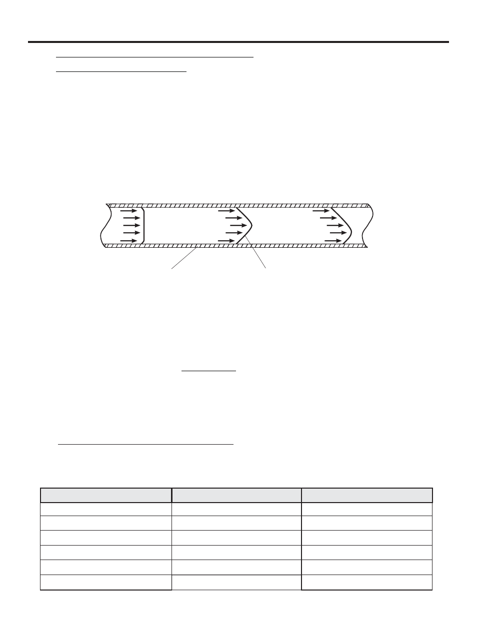
Fig. 2
! The F-2000 accuracy is based on steady, undisturbed flow with a fully developed turbulent flow profile.
Pulsating, swirling and other disruptions in the flow stream will effect the meters accuracy.
! There are two basic types of flow profiles; turbulent and laminar (see figure 2).
Turbulent flow exists when the speed of the fluid flowing in the pipe is nearly constant across the entire width of
the pipe. This is typical of low viscosity fluids like water, flowing at high velocity.
Laminar flow exists when the speed of the fluid flowing in the center of the pipe is greater than the speed of the
fluid at the outer edge near the pipe wall. This is typical of high viscosity fluids flowing at low velocity. Because
the F-2000 is measuring the fluid near the pipe wall only (especially in larger pipe sizes), a constant flow velocity
across the flow stream is required.
3.0
PIPE INSTALLATION REQUIREMENTS
3.1
Flow Stream Requirements
The F-2000 accuracy is affected by disturbances such as pumps, elbows, tees, valves in the flow stream.
Install the meter in a straight run of pipe as far as possible from any disturbances. The distance required for
accuracy will depend on the type of disturbance. (see figure 3 and 4).
3.1
Minimum Pipe Length Requirements
Type Of Disturbance
Minimum Inlet Pipe Length
Minimum Outlet Pipe Length
Flange
10 X Pipe Inside Diameter
5 X Pipe Inside Diameter
Reducer
15 X Pipe Inside Diameter
5 X Pipe Inside Diameter
o
20 X Pipe Inside Diameter
5 X Pipe Inside Diameter
90 Elbow
o
25 X Pipe Inside Diameter
5 X Pipe Inside Diameter
Two 90 Elbows -1 Direction
o
40 X Pipe Inside Diameter
5 X Pipe Inside Diameter
Two 90 Elbows -2 Directions
50 X Pipe Inside Diameter
5 X Pipe Inside Diameter
Pump Or Gate Valves
Pipe Cross Section
Flow Velocity Profile
Fully Developed
Turbulent Flow
Laminar
Flow
Disturbed Flow
(due to swirling)