C-1700n, Caution, 3 how to install the tubing and fittings – Blue-White C-1700N CHEM-FEED Diaphragm Pump User Manual
Page 6: Fig. 4.5 wiring diagram - fixed timers, Fig. 4.7 footvalve assy, Fig. 4.6
4.3
How To Install the Tubing and Fittings
4.3.1
Inlet Tubing - Locate the inlet fitting of the pump head, see fig 4.6. Remove the tube nut. Push the
clear PVC suction tubing onto the compression barb of the fitting. Use the tube nut to secure the tube.
Hand tighten only.
4.3.2
Footvalve/Strainer -Trim the inlet end of the suction tubing so that the strainer will rest vertically
approximately one inch from the bottom of the solution tank. This will prevent sediment from clogging
the strainer. Slip the ceramic weight over the end of the suction tube. Press the footvalve/strainer into
the end of the tube. Secure the ceramic weight to the strainer. Drop the strainer into the solution tank.
Be sure the footvalve does not lay horizontally on the bottom of the solution tank.
4.3.3
Outlet Tubing - Locate the outlet fitting of the pump head, see fig 4.6. Remove the tube nut. Push the
opaque outlet (discharge) tubing onto the compression barb of the fitting. Use the tube nut to secure the
tube. Hand tighten only.
Trim the other end of the outlet tube leaving only enough slack to connect it to the Injection/Check valve
Fitting (see below). Increasing the length of the outlet tube increases the back pressure at the pump head,
particularly when pumping viscous fluids.
Keep the inlet and outlet tubes as short as possible.
C-1700N
C-1700N
Page 6
Page 7
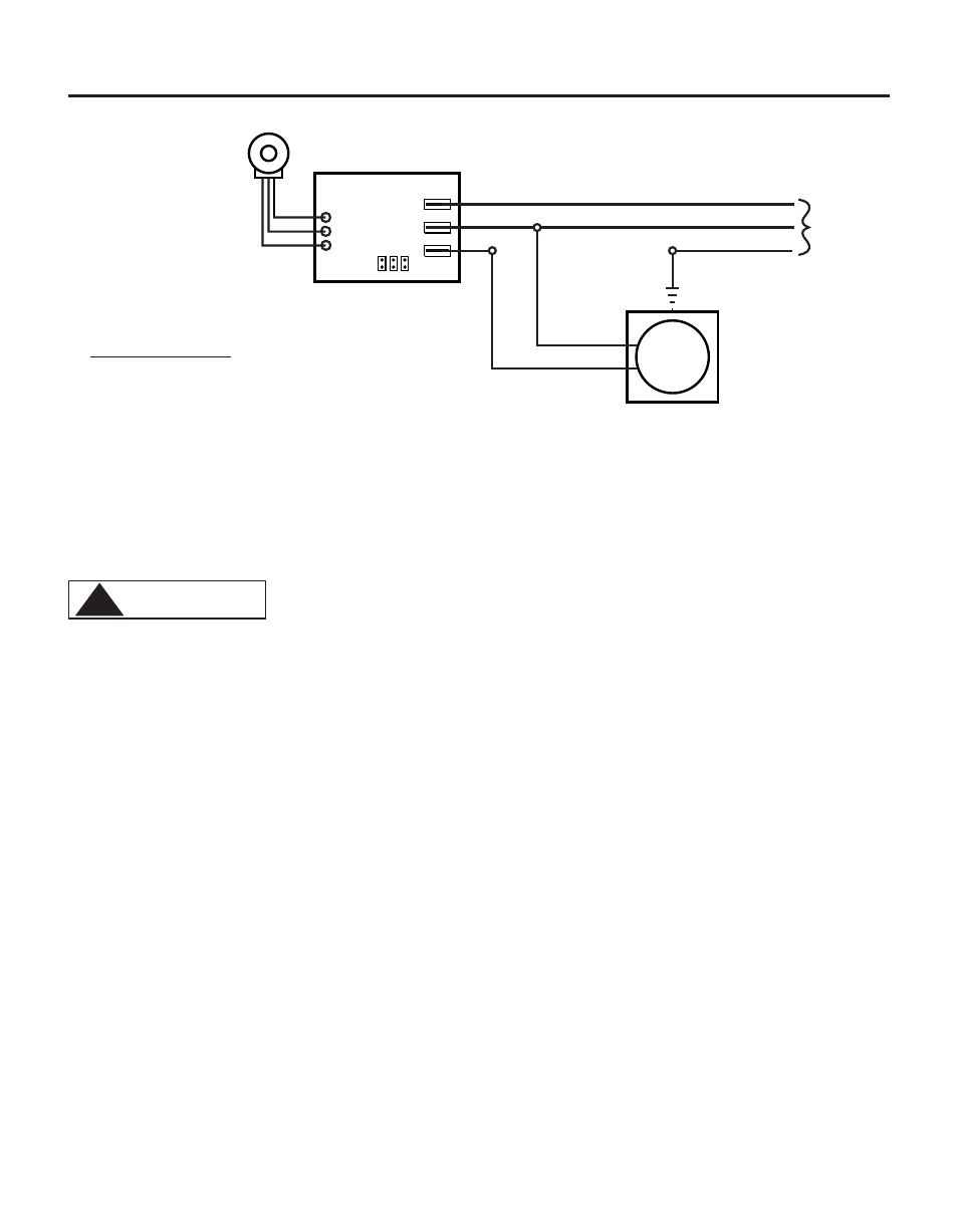
FIG. 4.5 WIRING DIAGRAM - FIXED TIMERS
(factory Setting)
Cycle Adjustment
Potentiometer
T3
T2
T1
AC
Input
Power
Hot
Common
Ground (green)
Timer
Board
Hot
Neutral
AC/LOAD
AC
LOAD
JB2 JB3
JB1
AC
Motor
JB1, JB2, JB3 = Voltage Selector Jumpers
Jumpers Configuration
Install JB2 & JB3, (JB1 left open) = 24 V AC input
Install JB1 & JB3, (JB2 left open) = 115 V AC input
Remove all jumpers (JB1, JB2, & JB3 left open) = 220V, 230 V AC input
FootValve
Sub-Assembly
(in vertical position)
Ceramic
Weight
Suction Tubing
Footvalve Adapter
O-Ring
Ceramic Ball
O-Ring
Footvalve Body
Footvalve Strainer
FIG. 4.7 FOOTVALVE ASSY.
4.3.4
Injection/Check Valve Fitting Installation - The Injection/Check valve fitting is designed to install
directly into either 1/4” or 1/2” female pipe threads.
Install the Injection/Check valve directly into the tee fitting. Do not install the fitting into a pipe stud
and then into the tee. The solution must inject directly into the flow stream.
Use PTFE thread sealing tape on the pipe threads. Push the opaque outlet (discharge) tubing onto the
compression barb of the Injection/Check valve fitting. Use the tube nut to secure the tube. Hand tighten
only.
Injection/Check valve fitting will require periodic cleaning, especially when injecting fluids that calcify
such as sodium hypochlorite. These lime deposits and other build ups can clog the fitting increasing the
back pressure and interfering with the check valve operation. See section 6.0.
FIG. 4.8
INJECTION/CHECK VALVE
TEE INSTALLATION AND EXPLODED VIEW
Discharge Tubes
(Rigid P.E.)
Outlet Adapters
Tube Nuts
Inlet Adapter
(2X)
Tube Nut
(2X)
Suction Tubings
(clear PVC)
FootValves
FIG. 4.6
Pump Head
bracket
Adjustment Knobs
(cam type mechanism)
Proper eye and skin protection must be worn when installing and
servicing the pump.
!
CAUTION