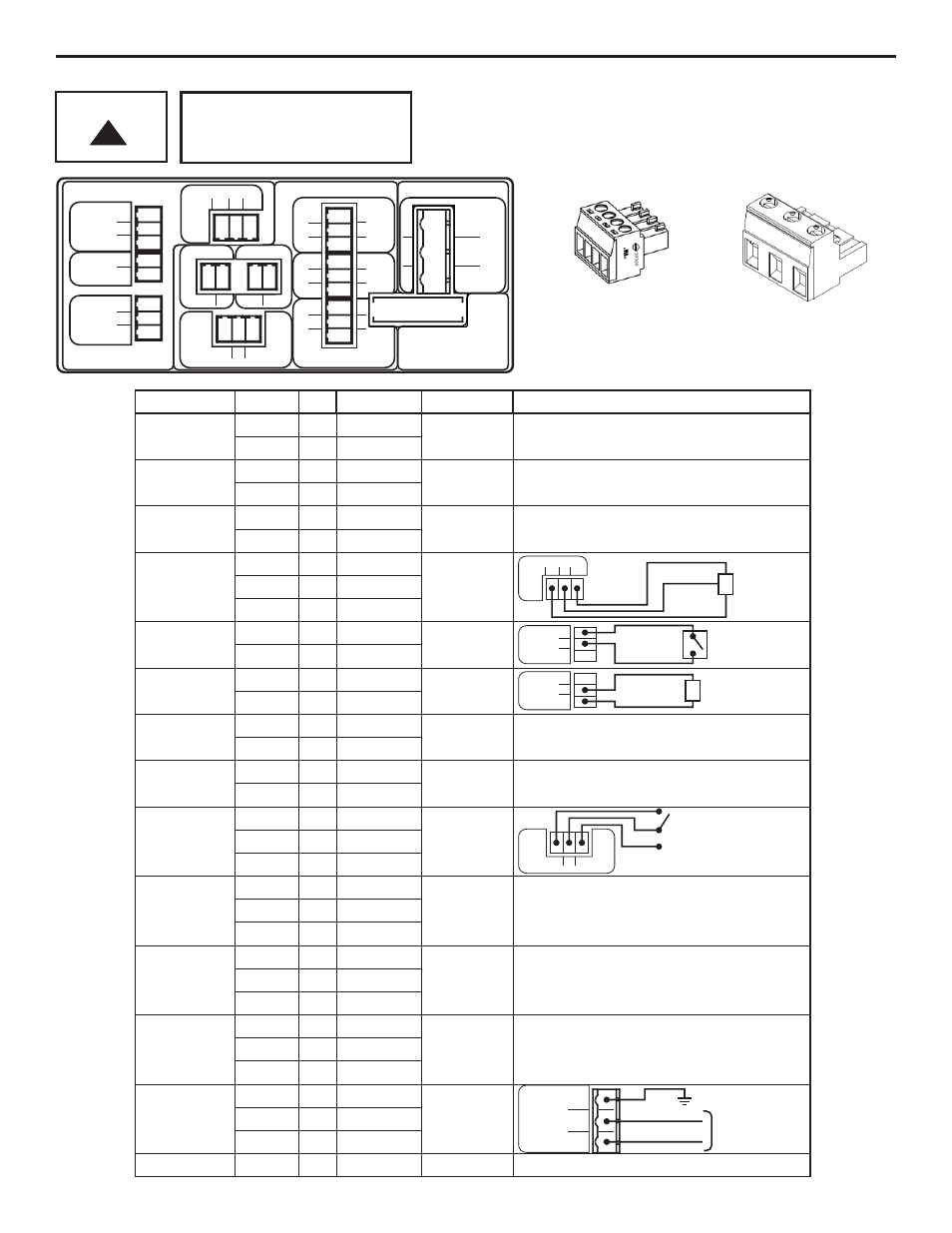
1 wiring terminals and i/o schematics, Warning flex-pro, T2 t4 – Blue-White FLEX-PRO A4 ProSeries Peristaltic Pump User Manual
Page 9: T6 power, T8 t9
Risk of electric shock – cord connected models are supplied with a grounding
conductor and grounding-type attachment plug. To reduce risk of electric shock, be
certain that it is connected only to a properly grounded, grounding-type receptacle.
Electrical connections and grounding (earthing) must conform to local wiring codes.
Be certain that a grounding conductor is connected to terminal T11-1 located in the
wiring compartment.
Risk of electric shock - Disconnect electricity before removing the wiring
compartment cover.
Page 9
OUTPUT
INPUT
3
1
2
T3
DRY
RMT
COM
1
2
3
T1
PULSE
GND (-)
4-20 (+)
0-10 (+)
+15 VDC
1
2
T2
T4
3
1 2
(+)
FVS
SIG
(-)
2
1
FREQ.
(-)
(+)
T5
1 2
4-20
mA
T6
POWER
FUSE 5A SLOW BLOW
(20 X 5MM)
F1
2
3
1
GROUND
N EUTRAL
(COMMON)
LINE
(HOT)
T11
N.C.
COM
N.O.
N.O.
COM
N.C.
CC3
CC2
T8
T9
3
1
2
3
1
2
3
1
2
CC1
N.O.
COM
N.C.
T10
1 2 3
N.C. COM. N.O.
RELAY
OUT
T7
(-)
(+)
5.1
Wiring Terminals and I/O Schematics
NOT USED
FUNCTION
TERMINAL PIN #
RATING
ELECTRICAL SP.
T1
T1
T1
T1
T2
T1
INPUT:
FVS (FLOW
VERIFICATION
SENSOR)
T4
T4
T4
(+) POSITIVE
3
2
1
2
1
2
1
2
3
(-) NEGATIVE
(+) POSITIVE
(-) NEGATIVE
(+) POSITIVE
(-) NEGATIVE
(+) POSITIVE
SIGNAL
(-) NEGATIVE
INPUT:
REMOTE
START / STOP
(DRY CONTACT C.)
INPUT:
REMOTE
START / STOP
(WET CONTACT C.)
OUTPUT:
RELAY, 10 AMP
INPUT:
POWER
FUSE
T3
T3
1
2
T3
T3
2
3
T6
T6
2
1
T5
T5
2
1
(+) POSITIVE
(-) NEGATIVE
(+) POSITIVE
(-) NEGATIVE
T7
1
T7
T7
2
3
NORM. CLOSED
COMMON
NORM. OPEN
T8
1
T8
T8
2
3
NORM. OPEN
COMMON
NORM. CLOSED
T9
1
T9
T9
2
3
NORM. OPEN
COMMON
NORM. CLOSED
T10
1
T10
T10
2
3
NORM. OPEN
COMMON
NORM. CLOSED
T11
1
T11
T11
2
3
GROUND
NEUTRAL
LINE (HOT)
F1
NA
5 AMP
6 TO 30 VOLT DC
1 AMP MAX.
6 AMP MAX AT
250 VAC,
5 AMP MAX AT
30 VOLT DC
5A SLOW BLOW
(20 X 5MM)
(-) NEGATIVE
(+) POSITIVE
(+) POSITIVE
(-) NEGATIVE
NO VOLTAGE
96 TO 264 VOLT AC,
50 / 60 HZ
A3 = 220W
A4 = 350W
T4
3
1 2
(+)
FVS
SIG
(-)
RED (+)
BARE
BLACK (-)
3
1
2
T3
DRY
RMT
COM
3
1
2
T3
DRY
RMT
COM
(+)
(-)
(+)
(-)
1 2 3
N.C. COM. N.O.
RELAY
OUT
T7
NO
C
NC
SWITCH LOAD
10 AMP MAX @ 250V AC
8 AMP MAX @ 30V DC
2
3
1
GROUND
N EUTRAL
(COMMON)
LINE
(HOT)
T11
EXTERNAL DEVICE
6 TO 30V DC
OPEN CIRCUIT
IMPEDANCE MUST
BE GREATER THAN
50K OHM
BLUE-WHITE
FVS SENSOR
96 TO 264 VOLT AC,
50 / 60 HZ
A3 = 220W
A4 = 350W
Risk of electric shock - All
wiring must be insulated
and rated 300V minimum.
!
WARNING
Flex-Pro
Terminals T1 thru T10
Plug type
16 - 24 AWG
Power Input Terminal T11
Plug type
14 - 30 AWG
NOT USED
NOT USED
NOT USED
NOT USED
NOT USED
NOT USED
NOT USED