Condensing units cu 1 – 4, Field connections, Condensing units – Airedale Condensing Units (CU) 3kW - 80kW User Manual
Page 11: Microprocessor controlled (ad05), System field connections for ad05 controlled units, Electro-mechanically controlled units, Cooling only units, Heat pump units
Condensing Units
CU 1
– 4
11
Condensing Units
11
Technical Manual : 904-020 v1.3.0 02_13
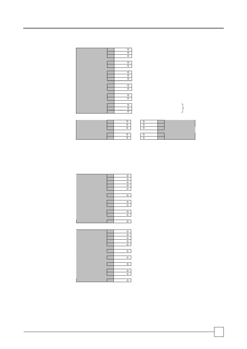
Field Connections
MICROPROCESSOR
CONTROLLED (AD05)
L1
N
Mains Incoming 230/1/50
E
S1A
Communication Connection
S1B
To Indoor Unit (Microprocessor Only)
COOL
COM
HEAT
External Control of Cool/Heat mode (Volt Free)
(1)
A3
Optional Auxiliary Alarm
A3
Volt Free Input (Normally Closed = Healthy)
DS1
Defrost Status Indication
DS2
Volt Free Contact (Normally Closed = Defrosting)
CCA
Common
CA1
Normally Closed Contact
CONDENSING UNIT
CA2
Normally Open Contact
Common Alarm Changeover
Volt Free Contacts
SYSTEM FIELD
CONNECTIONS FOR
AD05 CONTROLLED
UNITS
L1
L1
N
N
E
E
S1A
S1A
INDOOR UNIT
S1B
S1B
AD05 CONTROLLED
OUTDOOR UNIT
(1)
The microprocessor (AD05) controlIed condensing unit may be matched to non Airedale indoor
air handling units.
A contact can be closed across either the Cool and Common or Heat and Common terminals.
Ensure that the cooling and heating cannot be initialised simultaneously.
ELECTRO-MECHANICALLY CONTROLLED UNITS
Cooling Only Units
L1
L2
L3
Mains Incoming 230/1/50 or 400/3/50
N
E
34
Compressor Signal From Indoor Unit
576
577
Cooling Signal From 24vac controlled Indoor Unit
589
502
589/502 Volt Free Contact for Unit Trip Indication
CU.1 - 4
N1
Control Neutral (if required)
Heat Pump Units
L1
L2
L3
Mains Incoming 230/1/50 or 400/3/50
N
E
34
Compressor Signal From Indoor Unit
35
Cooling Signal From Indoor Unit
36
Defrost Signal From Indoor Unit
589
502
589/502 Volt Free Contact for Unit Trip Indication
CUH. 1 - 4
N1
Control Neutral (if required)