Warning – Advanced Protection S50A User Manual
Page 3
Page 3
The voltage rating of the device and system must always be
verified before energizing the SPD. All electrical connections
should be performed by a qualified (licensed) electrician. All
wiring must comply with the National Electrical Code (NEC)
and applicable local codes.
• Maintenance of this Surge Protective Device should
be performed by qualified electrical personnel only.
• During normal operation, hazardous voltages are
present inside the unit.
• When servicing this unit, be sure to follow all electrical
safety precautions.
• All power sources to this unit should be locked off
before servicing. This will prevent the risk of receiving
an electrical shock.
WARNING
VERIFY ALL POWER CIRCUITS ARE DE-ENERGIZED
BEFORE MAKING CONNECTIONS
!
S50A is a Type 1 SPD. S50A is suitable for use almost
anywhere (not as a plug-in SPD). Type 1 SPDs are
evaluated more rigorously by UL 1449 for 2008 NEC®
Article 285 compliance. Type 1 SPDs and their connecting
leads have been evaluated for line side applications
without need for supplemental overcurrent protection.
Type 1 SPDs include internal overcurrent protection. As a
generalization, there are practical maintenance reasons for
installing on the load side of the main overcurrent device
(i.e. Type 2 installation). When connected on load side of
main disconnect, we recommend connecting via a 30A
circuit breaker due to 10 AWG conductors. The circuit
breaker serves as a disconnect switch and provides NEC®
imposed short circuit protection to the conductors in Type
2 or 4 applications. (cUL units are Type 2 due to different
cUL criteria.)
Installation
Pre-Plan your installation. You need to accomplish the
following:
• Meet all National and Local codes (NEC
®
Article
285 and UL 1449 address SPDs)
• Confirm System voltage to SPD voltage (120V
SPD will fail instantly on 240V, 277V, etc.)
• Mount SPD as close to panel or equipment as
possible to keep leads short (long leads hurt
performance substantially)
• Ensure leads are as short and straight as
possible, including neutral. If using a breaker,
use a breaker position that is close to the SPD
and the panel’s neutral
• If using a breaker, recommended breaker size is
30A due to 10 AWG conductor
• Make sure system is grounded per NEC
®
and
clear of faults before energizing SPD (inadvertent
system problem may fail SPD).
• Never Hi-Pot test Any SPD (will prematurely fail
SPD)
1. Use voltmeter to check voltages and ensure correct
SPD. See Data Sheet for specs & wire-outs
2. Determine Mounting method (See Figure 2) –
weather resistant equipment may be required
3. Remove power from panel/source. Confirm panel/
source is deenergized.
4. Identify breaker location and SPD location. Position
SPD such that LED is best visible.
5. Mount SPD – weather resistant applications require
additional sealing, o-rings, etc. (not included)
- Remove an appropriately sized knockout from
panel.
- Connect conductors as appropriate – short and
straight as possible
6. Label or mark conductors as appropriate (neutral:
white, energized: black)
7. Make sure system is bonded per NEC
®
and is clear
of hazards or faults before energizing (N-G bonding
not per NEC
®
will fail SPDs: #1 cause of SPD
failures)
8. Energize and confirm proper operation of green LED
indicator and/or options.
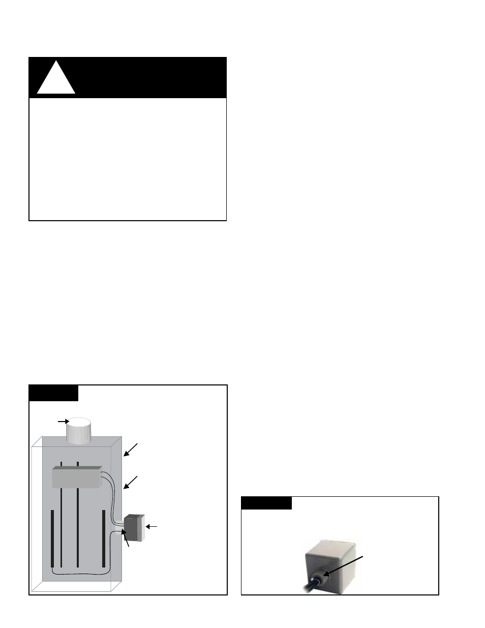
A
B
G
N
BREAKER
Typical Panel Installation
(Type 1 or individual equipment installations may vary)
• Use closest breaker to
SPD
• Locate SPD close to
intended breaker
• Keep Leads Short as
Possible
• Avoid Sharp Bends
• Outdoor installation requires
appropriate weather sealing
at nipple (gasket, sealing
conduit, etc.)
To Protected
Loads
Figure 1
• Rotate S50A such
that LED indicator is
most visible
Sealing gasket: two choices
1.) At 3/4" nom. thread: ID is 1.05"
2.) At 0.14" high 'base step': ID is 1.25"
Figure 2