Ar ch ive d – Seametrics TX100-200-SERIES v.2 User Manual
Page 8
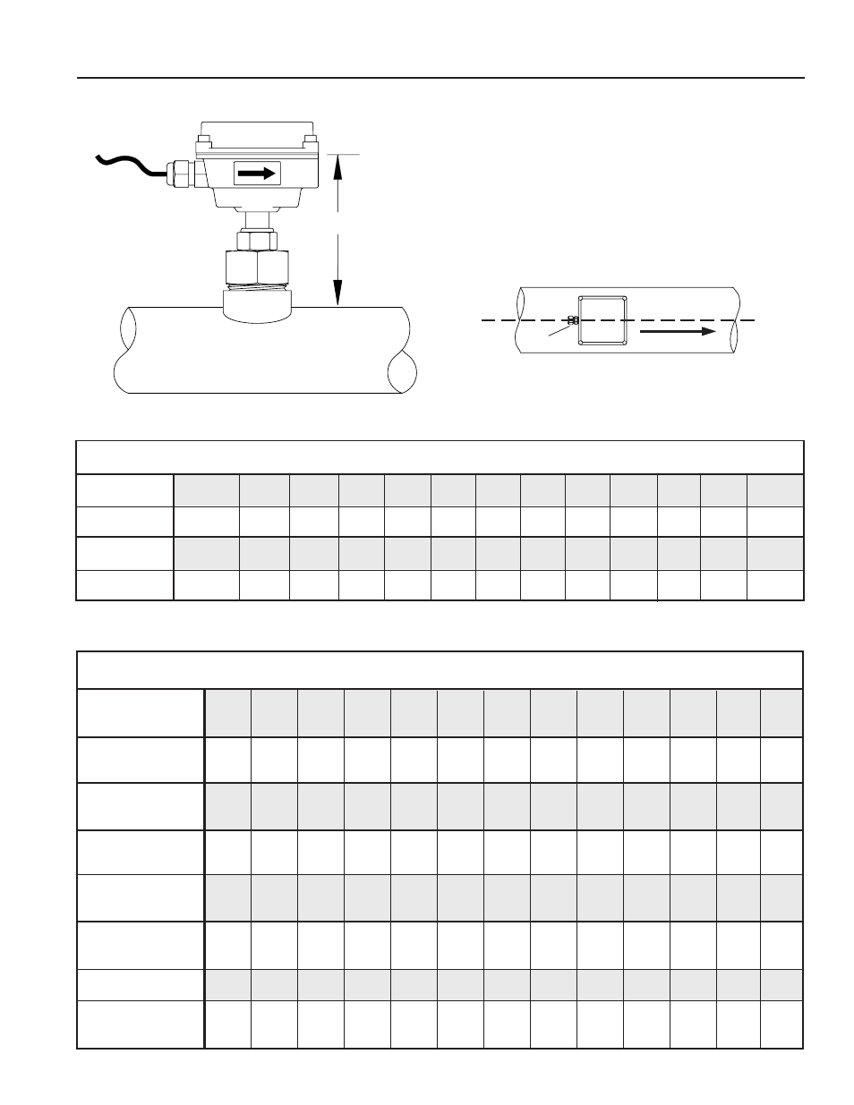
strain
relief
flOW
Page 6
INSTallaTION
Proper Depth Setting.
It is important for accuracy that the
sensor be inserted to the correct depth into the pipe.
1. In Table 1, find Dimension C for your sensor model
and pipe size. Subtract wall thickness of your pipe
(Table 2) to calculate Dimension D.
2. Measuring from the outside of the pipe to the joint in
the housing, as shown, adjust the sensor to
Dimension D and hand-tighten compression nut.
3. Align the conduit housing with the centerline of the
pipe, as shown below. Be sure the arrow on the housing
points in the direction of flow.
4. Check Dimension D one more time.
5. Tighten the compression nut fully.
"D"
TaBlE 2: PIPE Wall THIckNESS
TaBlE 1: DIMENSION “c”
NOMINal PIPE SIzE
3”
4”
6”
8”
10”
12”
14”
16”
18”
20”
24”
30”
36”
9.16
9.08
8.99
8.82
8.48
8.14 7.80
7.46
6.78
-
-
-
-
14.16
14.08 13.99 13.82 13.48 13.14 12.80 12.46 11.78 10.42 9.40
9.38
-
16.00
15.80 15.70 15.50 15.10 14.80 14.50 13.80
-
-
-
-
-
19.95
19.85 19.65 19.45 19.15 18.85 18.45 17.75 16.45 15.45 14.35
-
-
TX101
TX201
TX115
TX215
PVc/Steel
Sch. 40
PVc/Steel
Sch. 80
Stainless
Steel (10S)
Stainless
Steel (40S)
copper Tubing
(Type l)
copper Tubing
(Type k)
Brass Pipe
Duct. Iron
(class 52)
NOMINal PIPE SIzE
3”
4”
6”
8”
10”
12”
14”
16”
18”
20”
24”
30”
36”
0.216 0.237 0.280 0.322 0.365 0.406 0.438 0.500 0.562 0.593 0.687
0.300 0.337 0.432 0.500 0.593 0.687 0.750 0.843 0.937 1.031 1.218
0.120 0.120 0.134 0.148 0.165 0.180 0.188 0.188 0.188 0.218 0.250 0.312 0.312
0.216 0.237 0.280 0.322 0.365 0.375 0.375 0.375 0.375 0.375 0.375 0.375 0.375
0.090 0.110 0.140 0.200 0.250 0.280
0.109 0.134 0.192 0.271 0.338 0.405
0.219 0.250 0.250 0.312 0.365 0.375
0.280 0.290 0.310 0.330 0.350 0.370 0.390 0.400 0.410 0.420 0.440 0.470 0.530
AR
CH
IVE
D