Ar ch ive d – Seametrics TX100-200-SERIES v.2 User Manual
Page 12
LT-65200050-C
6/25/10
TROUBlESHOOTING and REPaIR
Seametrics Incorporated • 19026 72nd avenue South • kent, Washington 98032 • USa
(P) 253.872.0284 • (f) 253.872.0285 • 1.800.975.8153 • www.seametrics.com
CAUTION! Never attempt to remove a
flow sensor when there is pressure in
the pipe. Loosen the compression nut
slowly to release any trapped pressure.
If fluid sprays out when removing the
sensor, stop turning and depressurize the pipe. Fail-
ure to do so could result in the sensor being thrown
from the pipe, resulting in damage or serious injury.
Repair
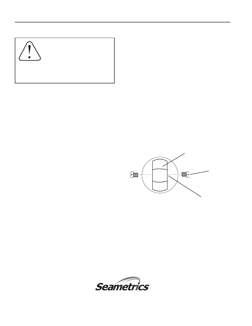
*NOTE: Described here is the rotor/shaft/bearing configuration for
the carbide shaft model. On ceramic shaft models the shafts are in
the screws and the bearings are in the rotor. Follow the same basic
procedure above.
Rotor Replacement.
* Rotors are easily field-replaced.
Shaft and rotor are a single unit, and are not replaced
separately. If replacement is due only to normal shaft
wear, bearing replacement is probably not necessary. If
the rotor has been damaged by impact, the bearings should
also be replaced. Rotor and bearings can be ordered as
a kit (see parts listing). Follow these steps:
1. Unscrew the threaded bearing housings to expose the
shaft ends. If bearings are being replaced, back them
completely out.
2. Remove the rotor. Put the new rotor in its place.
3. Thread in one bearing housing part way, then the
other. Take care to start the end of the shaft into
the bearing hole before tightening further.
4. Screw in bearing housings until they bottom.
Note: Do not use excessive force.
5. Check for free spin. Blowing lightly on the rotor
should result in it spinning rapidly and coasting
to a smooth stop.
Shaft
Turbine Rotor
Bearing*
Housing
The flow sensor has only one moving part, the rotor. If
this is turning properly and there is no signal, the Hall-
effect sensor is not operating properly. To check the
signal, apply 12 Vdc regulated* power to the red (+)
and black (-) leads. Set a multimeter to voltage reading.
Put the positive multimeter lead on the red wire and the
negative lead on the white wire. Slowly turn the rotor.
Voltage reading should swing between +12 Volts and 0
Volts as the rotor turns. If it does not, the Hall effect
sensor is not working properly. Checking for continuity
is not a useful test of these sensors.
*NOTE: An unregulated power supply can exceed max voltage
of micro powered sensor (gray cable) and damage sensor.
All Seametrics flow sensors are repairable, and can be
returned to the factory or distributor for repair.
Please first obtain a Return Material authorization
(RMa) number.
Troubleshooting
AR
CH
IVE
D