Ar ch ive d – Seametrics TX100-200-SERIES v.2 User Manual
Page 10
Page 8
(0.2)
(0.5)
(1.0)
(2.0)
(5.0)
(10.0)
(20.0)
(30.0)
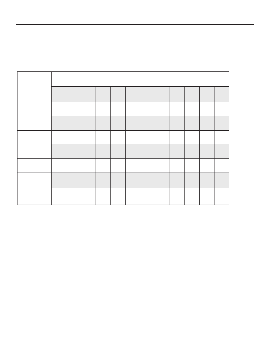
TABLE 4: Flow Rates converted from Feet/Sec to Gallons/Minute at various velocities: Schedule 40 pipe
Nominal pipe size
Feet / Sec
▲
3"
4"
5"
6"
8"
10"
12"
16"
24"
36"
38"
48"
4.6
7.9
12.5
18
31.2
49.1
70
125
259
600
670
1090
11.5
19.8
31.2
45
78
123
174
275
627
1460
1770
2820
23
39.7
62.4
90
156
246
349
551
1250
2910
3530
5640
46.1
79.4
125
180
312
492
698
1100
2510
5830
7070 11280
115
198
312
450
780
1230
1740
2750
6270 14570 17670 28200
230
397
624
900
1560
2460
3490
5510 12530 29140 35350 56400
461
794
1250
1800
3120
4920
6980 11020 25060 58270 70700 112800
691
1190
1870
2700
4680
7370 10470 16520 37600 87410 106050 170000
flow Range.
These sensors are designed to operate at
flow velocities of 0.2 to 30 feet per second (see Table 4,
below). If erratic readings are encountered at low flows,
check the chart to see if flow is below minimum for the pipe
size. The standard shaft and bearings should have a long
life at continuous high flow.
OPERaTION
AR
CH
IVE
D