Ar ch ive d – Seametrics AG2000 v.1 User Manual
Page 3
Pair 1-Black
Pair 1-Red
Pair 3-Black
Pair 3-Red
DC30/DC35
Shielded Burial Cable,
3 Twisted Pairs,
22 AWG Stranded
Pair 2-Black
Pair 2-Red
Serial Output
Technician
Use Only
Pulse (-)
Pulse (+)
External Power
12-18Vdc
Vcc (-)
V (+)
Scaled Pulse
Output
Blue
Orange
White
Colored Sleeves*
*Colored Sleeves readily identify the 3 pairs.
If the cable needs to be cut back, the pair
identification is printed on each wire.
Drain Wire
(Connect to
Earth Ground)
Page 3
POWER SUPPLY and OUTPUTS
Battery Power (standard). The AG2000 is powered by
a non-rechargeable battery pack with an average lifespan
of 3 years. Lifespan varies somewhat based on usage
(less current is required during periods of empty pipe;
somewhat more when the pipe is full but there is no flow;
and the highest current draw occurs when the pipe is full
and flowing).
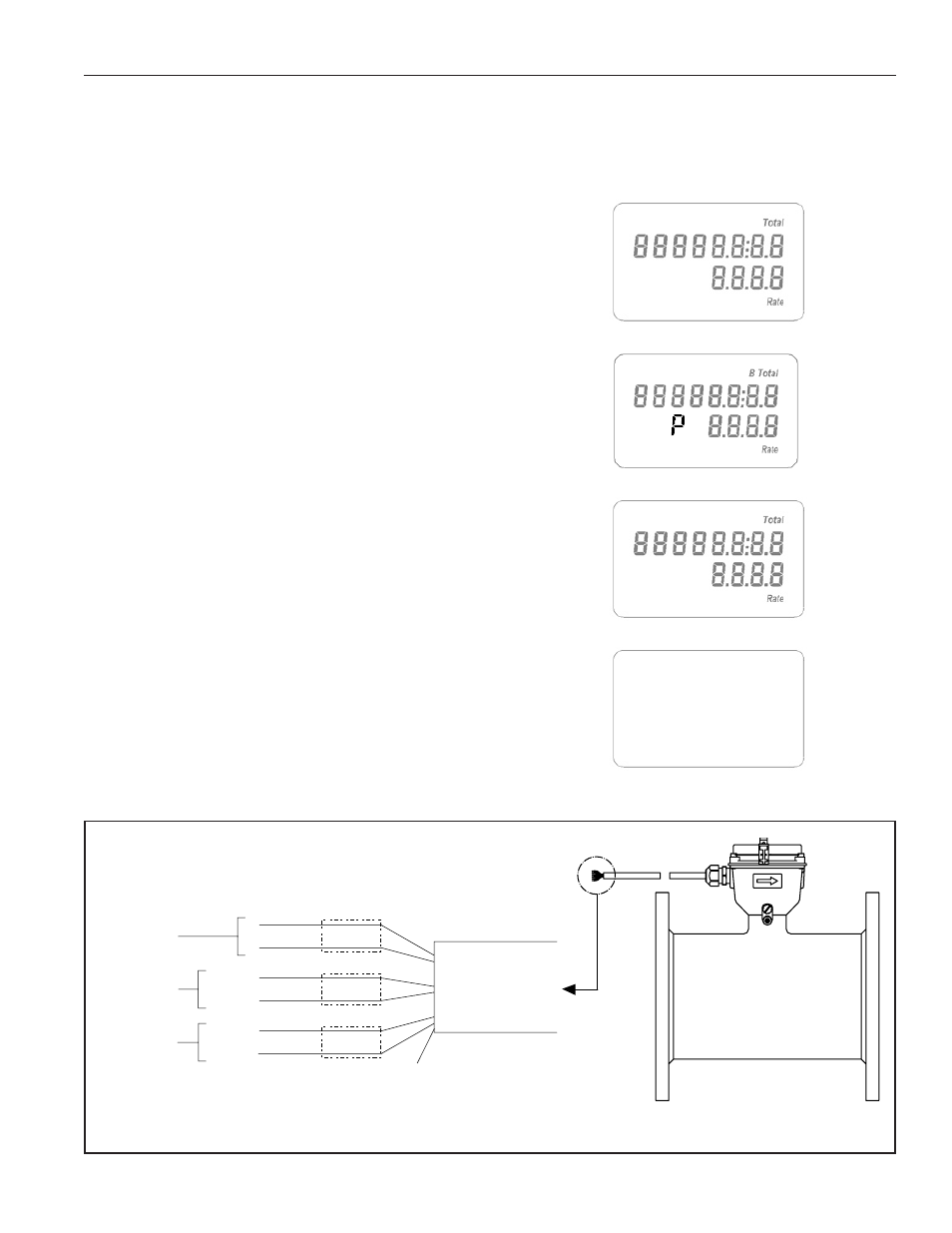
The display reads “Low Batt” when there is approximately
3 days of use left in the battery (see illustration at right).
Replacement instructions come with the custom battery
pack available from your dealer or SeaMetrics (Part
#31126).
External Power (optional). Where 7-24 Vdc power is
available, the life of the battery pack can be indefinitely
extended by the addition of an external power input cable.
When external power is used, the batteries serve as backup
in case of power failure. The display reads “P” to indicate
that external power is in use (see illustration at right).
When the display is reading numbers/letters but neither
the “Low Batt” or “P” symbol is displayed, the meter is
functioning normally under battery power (see illustration
at right). When the display is completely blank, the meter
is not powered (see illustration at right).
Solar Power (optional). In most areas of the US, a 12-
volt, 5 watt solar power unit (panel, charge controller and
battery) should suffice to operate the meter. In this case,
the internal batteries will serve as backup and battery life
will be conserved.
Optional Input and Outputs. An optional cable, factory-
installed or field-installed by an authorized individual,
provides power input, pulse output (for telemetry and data
logging functions), and serial output (for technician use in
custom telemetry applications). See diagram below.
Low
Batt
Low Battery Indicator
External Power Indicator
Battery Power
Display Reading. There are two lines to the display, the
bottom line for flow rate and the top line for accumulated
total. Measurement units are pre-ordered and factory-set
and can be changed in the field only by an authorized
individual.
Optional Input/Output Cable
No Power
AR
CH
IVE
D
(Includes Dates 7/19/06 to 1
1/06)