Seametrics IP100-200-SERIES User Manual
Page 9
Ensures full pipe
Keeps pipe full at sensor
Page 7
CONNECTION, OPERATION & REPAIR
CONNECTION
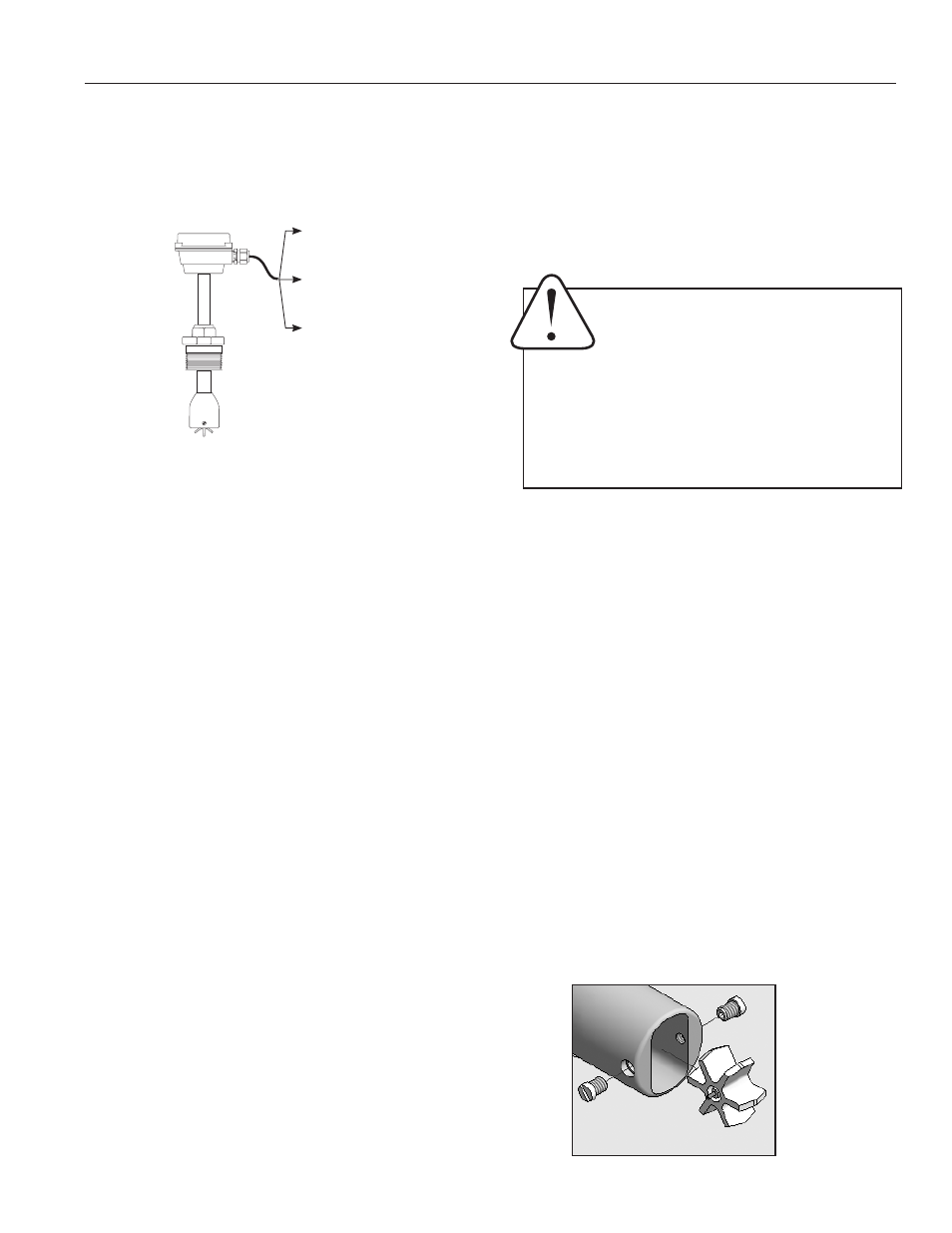
Sensors are supplied with 18 ft. (6m) of cable. For sensors with
no additional electronics, see diagram for color coding of con-
nections. For sensors with on-board electronics, see the manual
accompanying the electronic module.
Rotor Replacement.
Rotors are easily field-replaced. Shaft
and rotor are a single unit, and are not replaced separately.
If replacement is due only to normal shaft wear, bearing re-
placement is probably not necessary. If the rotor has been
damaged by impact, the bearings should also be replaced.
Rotor and bearings can be ordered as a kit, Part No. 25902.
Follow these steps:
1. Unscrew the threaded bearing housings to expose
the shaft ends. If bearings are being replaced,
back them completely out.
2. Remove the rotor. Put the new rotor in its place.
3. Thread in one bearing housing part way, then the
other. Take care to start the end of the shaft into
the bearing hole before tightening further.
4. Screw in bearing housings until they bottom.
Note
: Do not use excessive force.
5. Check for free spin. Blowing lightly on the rotor
should result in it spinning rapidly and coasting to
a smooth stop.
Calibration (“K-Factor”).
In order to properly process pulses from
the flow sensor, a number must be entered into the control to
which the sensor is connected. This number, called the K-factor,
is the number of pulses the sensor puts out per unit of fluid
passing through the pipe. It is normally provided for Seametrics
sensors in pulses per gallon, and is given on the chart “K-factors
for Various Pipe Sizes.” These numbers are based on extensive
testing, which has shown close agreement between different IP
sensors in the same installation. Typically, most K-factor error
can be attributed to installation variables, such as depth setting
and fitting configuration.
It is occasionally possible to field calibrate a sensor by catching
the fluid in a measured container and comparing with the number
of pulses recorded. (To record individual pulses, set the K-factor
on the control to 1.00.) This is especially desirable if the instal-
lation has less than the recommended length of straight pipe
upstream of the sensor.
OPERATION
Theory.
In principle, an insertion flow sensor measures the veloc-
ity of flow at one point in the pipe, and flow rate and total can be
inferred from this one point. Accuracy is decreased by any factor
which makes the flow at the measured point unrepresentative
of the entire flow stream. This includes distorted flow patterns
caused by upstream fittings too close to the sensor. The worst of-
fenders are fittings that increase the flow on one side of the pipe,
such as partially-opened gate or butterfly valves. Fluid moving in
a pipe does not all flow at the same velocity. Toward the center
of the pipe, fluid moves faster than at the wall, and the relation-
ship between the two changes as overall flow rate increases.
This change in the “velocity profile” can result in non-linearity,
which means that the K-factor that is correct for one flow rate
may be incorrect for another. The recommended depth settings
have been carefully chosen to minimize this source of error, and
should be followed carefully, especially in the smaller pipe sizes.
Flow Range.
These sensors are designed to operate at
flow velocities of 0.3 to 30 feet per second. (See chart for
conversion to gallons per minute.) If erratic readings are
encountered at low flows, check the chart to see if flow is
below minimum for the pipe size. The standard shaft and
bearings should have a long life at continuous high flow.
REPAIR
RED (+) 6-24 Vdc
WHITE (signal)
BLACK (-) Power
18' cable standard
Caution!
Never attempt to remove a flow
sensor when there is pressure in the pipe
unless it is specifically designed for hot
tap installation and removal. Loosen the
compression nut slowly to release any trapped pres-
sure. If fluid sprays out when removing the sensor,
stop turning and depressurize the pipe. Failure to
do so could result in the sensor being thrown from
the pipe, resulting in damage or serious injury.