Seametrics IP100-200-SERIES User Manual
Page 10
2
1
9
8
15
16
12
5
6
4
3
7
14
13
11
10
15
8
REPAIR & PARTS
Signal
The flow sensor has only one moving part, the rotor. If this
is turning properly and there is no signal, the Hall-effect sen-
sor is not operating properly. To check the signal, apply 12
Vdc regulated* power to the red (+) and black (-) leads. Set
a multimeter to voltage reading. Put the positive multimeter
lead on the red wire and the negative lead on the white wire.
Slowly turn the rotor. Voltage reading should swing between
+12 Volts and 0 Volts as the rotor turns. If it does not, the Hall
effect sensor is not working properly. Checking for continuity
is not a useful test of these sensors.
*NOTE: An unregulated power supply can exceed max voltage of
micro powered sensor (gray cable) and damage sensor.
All Seametrics flow sensors are repairable, and can be
returned to the factory or distributor for repair after a Return
Material Authorization (RMA) number has been issued.
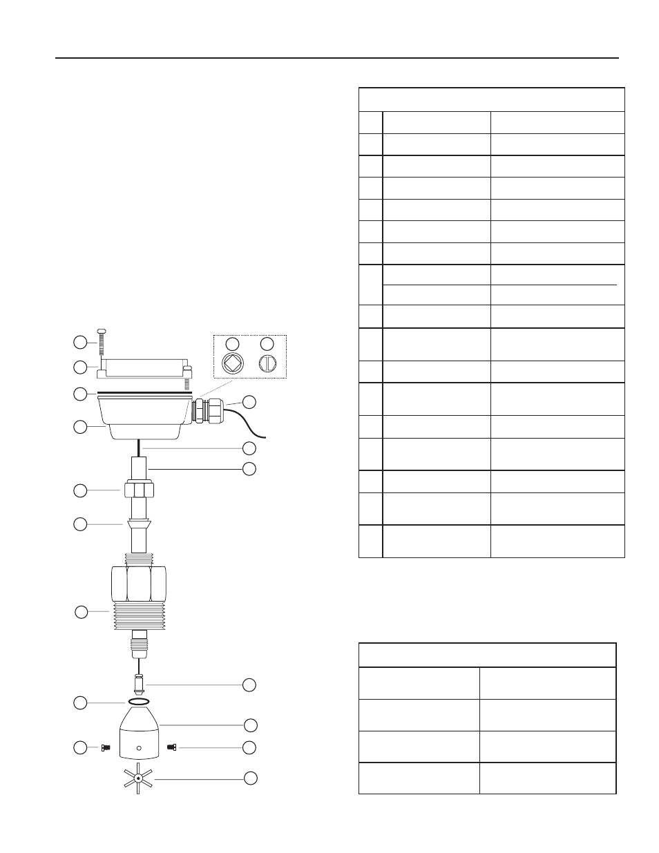
IP110/210 Parts
1
Upper housing assembly
100662
2
Gasket
100411
3
Lower housing
Not Field Replaceable
4
Housing screw (4 req'd)
100414
5
Plug, steel
100360
6
Plug, plastic
100364
7
Strain relief
101850
8
Pickup, Micropower (for FT415)
Pickup, Standard (for FT420)
100508
100419
9
Tube
Not Field Replaceable
10
Compression nut
100064 (Brass)
100084 (S/S)
11
Compression ferrule
100358
12
Adapter
100845 (Brass)
100846 (S/S)
13
Rotor housing O-ring (EPDM)
100218
14
Rotor housing
100068 (Brass)
100118 (S/S)
15
Jewel bearings (2 req)
100316
16
Rotor with shaft
100035 (Kynar/Tungsten Carbide)
100036 (Kynar/Ceramic)
17
Rotor repair kit
(includes of #15 & #16)
100317 (Kynar/Tungsten Carbide)
100043 (Kynar/Ceramic)
Page 8
Parts Explosion
HOT TAP: IP150/250 Parts (not shown)
Adapter fitting
100059 (Brass)
100082 (S/S)
Ball valve assembly
100069 (Brass)
100119 (S/S)
Collar, locking
100061 (Brass)
100116 (S/S)
Hex nipple, 2"
100066 (Brass)
100103 (S/S)