Appendix c, Installing the optional tachometer kit – Precision Control Systems DryIR 6030 User Manual
Page 22
Model 6030 Dry IR Drying System Instruction Manual
Appendix C
Installing the Optional Tachometer Kit
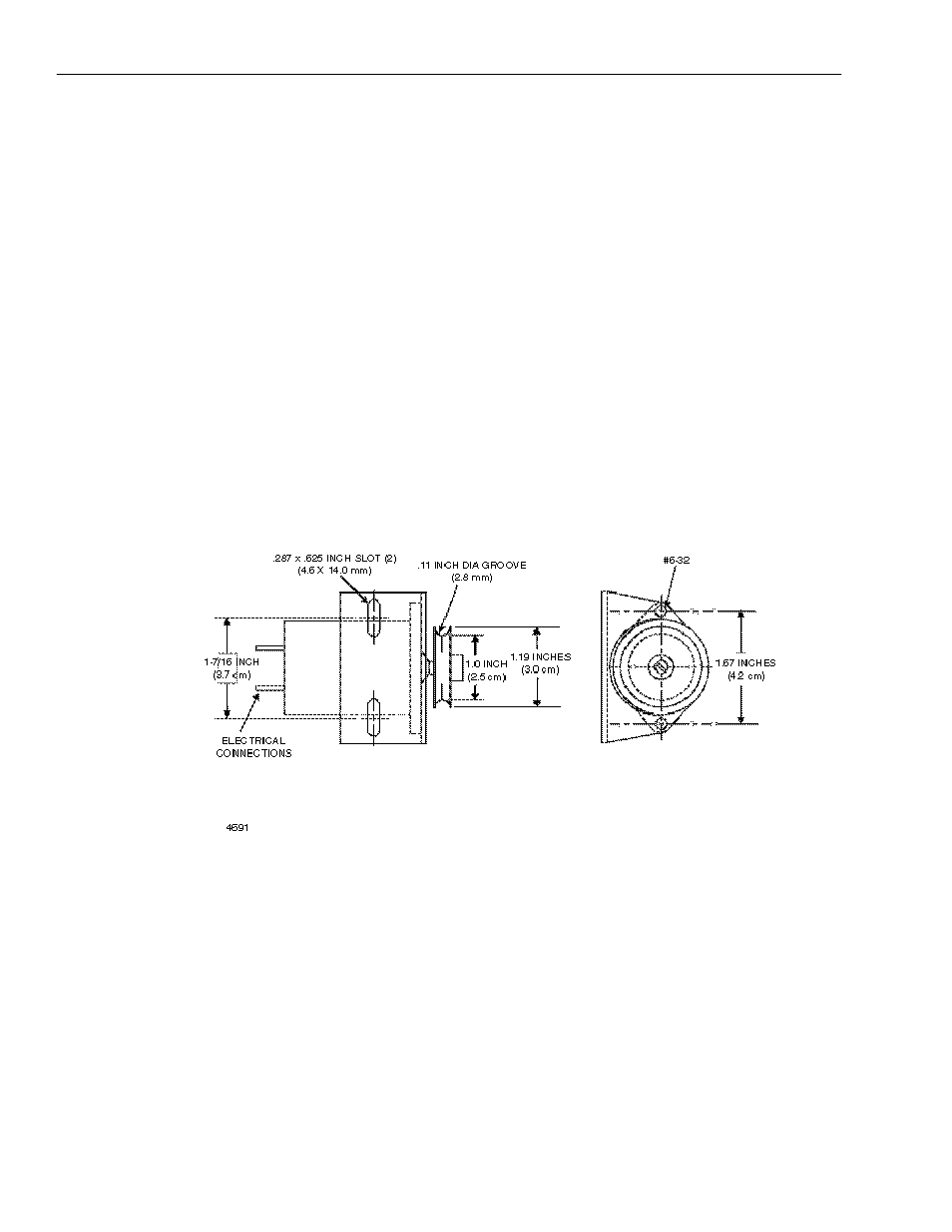
The dryer may be mounted on a variety of equipment configurations. If the tachometer supplied with
the Dry-IR system is used (Fig. C-1), it must be properly installed so that it will send a “speed signal”
to the control box ranging from zero volts when the conveyor is stopped to 10 volts when the
conveyor is at full speed. Doing so will enable the controller to operate properly, and provide the
widest range of heat control.
When a dual module system is ordered, the tachometer cable included has one end that connects to
the tachometer, and one connection to go into each of the drying modules.
The tachometer furnished with the Dry-IR system is a D.C. generator that creates a 5-volt output
when rotating at about 650 rpm. Getting the tachometer to rotate at 650 rpm when the conveyor is at
full speed requires that the correct size shaft or roller drive the O-Ring drive belt. The following two
sections explain how to determine the correctly sized driving shaft depending on the type of
equipment on which the dryer will be mounted.
Figure C-1. Tachometer and Mounting Bracket
When the potentiometer is adjusted and used in conjunction with the tachometer kit, the
potentiometer to output relationship remains the same as when run without the tachometer - the
potentiometer trim maximum output and tachometer are directly proportional to line speed. The line
speed dictates the dryer output, and the potentiometer further limits dryer output by controlling the
voltage applied to the dryer.
18