Installation – Precision Control Systems 3629C User Manual
Page 9
MODEL 3629C
5
04/10/2007
INSTALLATION
MOUNTING
The 50 Amp model 3629C controller is convection cooled and must be mounted with the fins aligned vertically on a
flat surface so that air may pass over the fins. Although larger model 3629C controllers are forced air cooled, it is
recommended that all controllers be mounted vertically with power terminals on top.
Allow at least 3" of space
between controllers for air to enter and exit. The controller should be protected from dust and dirt, and must
be located in an environment that does not exceed 55°C.
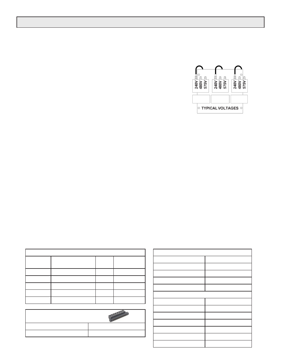
TRANSFORMER TAPS
If the line voltage input is to be changed, place the three fasten connectors
on the transformer taps to correspond with the voltage to be applied.
NOTE: The transformer may fail if all three of the connections to the taps
are not correctly placed. All fasten connectors must be moved to the same
corresponding voltage tab on each phase as shown in the sample illustration.
POWER CONNECTIONS
The line and load connectors on the various sizes of controllers are rated for use with copper conductors with 90°C or
higher insulation. The ratings are calculated for use in a 55°C ambient environment. Multiple connectors are provided
in larger controllers to use parallel conductors in each line and load. See
for the 'inline' and
'inside delta' line and load connections.
STARTUP
Before applying power, determine that the transformer taps are in the correct positions, that the power and load wiring
is correct, and electrical connections are tight. Set the command to zero and apply power to the controller. As the
command signal is increased, the load voltage.
It is recommended that the load and the controller be protected
with the proper rated fuses. See
section.
SCOTT-T TRANSFORMERS
Excessive voltage transients can occur when operating Scott-T transformers with an open or unloaded
secondary. It is recommended that Scott-T transformer be limited to 480 Volts maximum.
DELTA-WYE TRANSFORMERS
It is recommended that a Delta to 4-wire Wye transformer be used to power a 4-wire Wye load. Delta to 3-wire Wye
transformers are acceptable, but Wye to Wye transformers are not suited for use between the controller and load due
to transient conditions which may occur.
WIRE TERMINAL TORQUE RECOMMENDATIONS
TO AVOID FIRE OR DAMAGE TO EQUIPMENT, DETERMINE THAT WIRE CONNECTIONS ARE TIGHTENED TO
THE TORQUE SPECIFICATIONS BELOW AND THE CONNECTION SURFACES ARE FREE OF OXIDATION.
FRAME SIZE 50 & 80 AMPS
WIRE SIZE
INCH-LBS
14 to 10 ga
35
8 ga
40
6 to 4 ga
45
3 to 2 ga
50
FRAME SIZE 120 TO 1000 AMPS
WIRE SIZE
INCH-LBS
6 to 4 ga
100
2 to 1 ga
125
1/0 to 2/0
150
4/0 to 3/0
200
250 to 350 MCM
250
500MCM
300
WIRE LUG INFORMATION
FRAME
SIZE (A)
LUG
CONNECTIONS
LUG
WIRE SIZE
50-80
1 - per LINE/LOAD
USD
#2 - #14
120-160
1 - per LINE/LOAD
CA-6 250MCM - #6
200-425
2 - per LINE/LOAD
CA-6 250MCM - #6
500-750
2 - per LINE/LOAD
CA-7 500MCM - #0
1000
4 - per LINE/LOAD
CA-7 500MCM - #0
R
ECOMMENDED TIGHTENING TORQUE
FOR EDGE CARD CONNECTOR
:
W
IRE
S
IZE
(
AWG
)
T
ORQUE
14
TO
26
GA
4.4 - 5.5
IN
-
LBS