Command connections, Figure 14, When this signal remains high, it – Precision Control Systems 3629C User Manual
Page 15: Figure 12, Figure 13
MODEL 3629C
11
04/10/2007
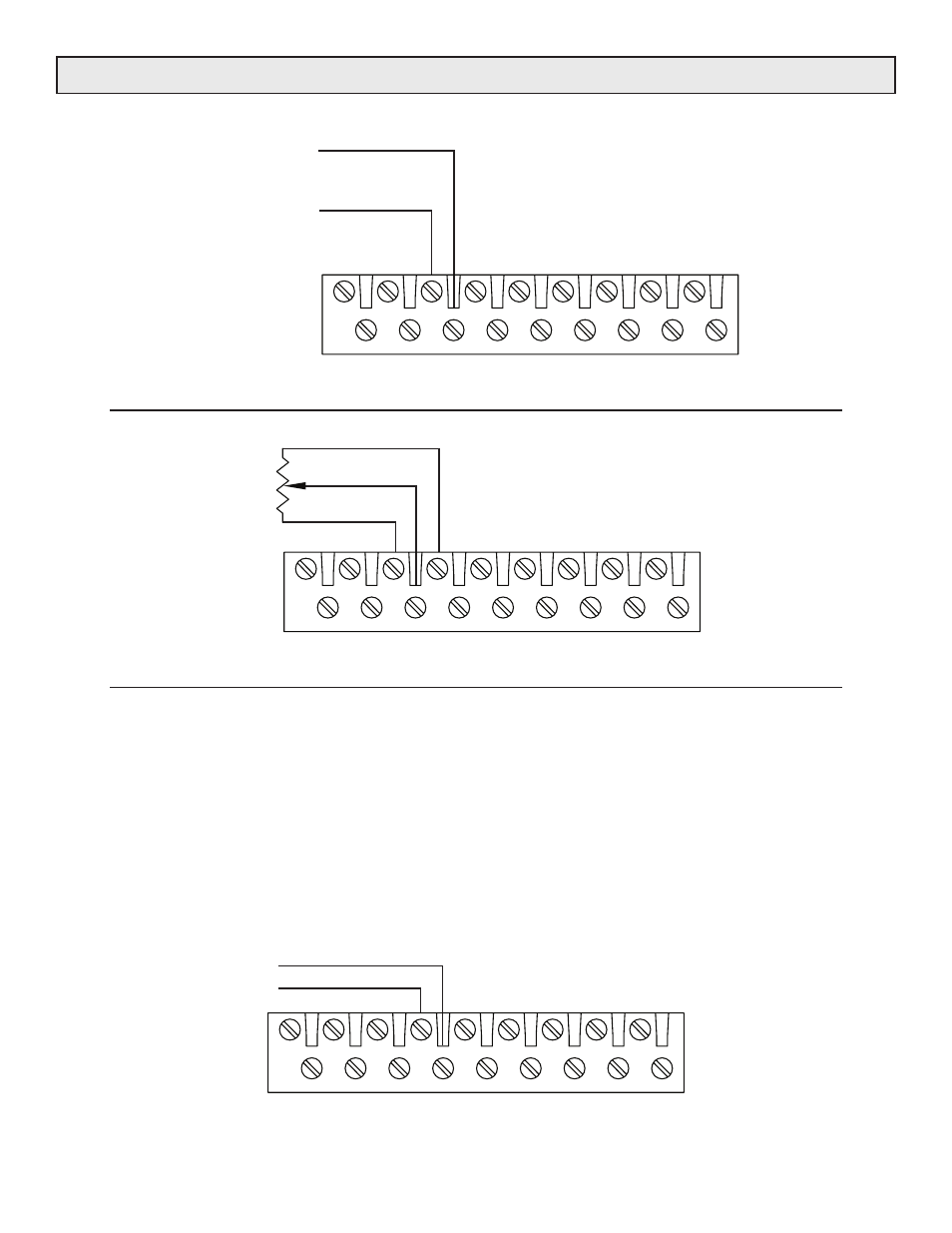
COMMAND CONNECTIONS
COMMON (-)
VOLTAGE OR
CURRENT
COMMAND SIGNAL
POSITIVE (+)
1
2
3
4
5
6
7
8
9
10
11
12
13
14
15
16
17
18
Figure 12. Voltage or current command connections.
CCW
CW
WIPER
I K
POT
1
2
3
4
5
6
7
8
9
10
11
12
13
14
15
16
17
18
Figure 13. Potentiometer command connections.
The
Controller Ready signal is controlled by an open
collector transistor which goes low with respect to Pin 12
when the controller is in the ready state.
Any of the following conditions will prevent the controller
from entering the ready state.
• Over current.
• One or more of the line phases is not present.
• One or more phases are not present on the firing circuit
board. (Circuit fuse may be cleared.)
• The phase lock is not enabled.
• The gate drive is not enabled.
• The Over Current Trip reset switch may be closed.
READY
5 V
1
2
3
4
5
6
7
8
9
10
11
12
13
14
15
16
17
18
Figure 14. Ready Output.