Installation: start up, Adjustments, Calibration – Precision Control Systems 1032 User Manual
Page 4
Model 1032
2 of 9
Part No. 5000095-1011-6 6/13/2003
Zero:
(Factory set to provide zero load voltage when a
zero command signal is applied) The zero
potentiometer is used to adjust the controller to
provide zero load voltage when the command is
zero.
Span:
(Factory set to provide 100% output with 100%
command) The span determines the load voltage
for a given command input.
Current Limit:
Factory set at 105% of rated current unless ordered
with a specific current limit setting. Counter-
clockwise rotation decreases the point at which
current limit occurs.
The span and zero have been adjusted at the
factory and should require no further adjustments.
If adjustments become necessary, the following
procedures should be used:
(see figure 8 on p. 8 for location of adjustments.)
1. Set the command signal to minimum and adjust
the zero potentiometer until the output is zero.
2. Set the command signal to maximum and adjust
the span potentiometer until the output is at the
desired maximum value.
3. The span and zero adjustments may interact.
It may be necessary to repeat steps 1 and 2.
Note: Loads with variable resistance may cause
the current limiting feature to limit the output of the
controller, which would appear as though the span
is not adjusted properly.
To test for current limiting, rotate the current limit
pot 1 turn counterclockwise. If the load current
decreases, the current limit is controlling the output.
The controller must be mounted on a vertical surface
such that the heat radiating fins are vertical, as
shown in fig. 2 on P.3 & fig. 4 on P.4. The controller
should be located in an environment that will not
exceed 135°F and is free of dust, dirt and moisture.
Figures 6 & 7 on P. 6 show power and control
connections. All wiring must be per local electrical
codes. The supply and load terminals will accept
aluminum wire from #2 to #8 and copper wires from
# 2 to #14.
The control transformer supplied with the controller
provides 24Vac to the circuit. This transformer
must be connected to the same electrical phase
from which the controller and load are connected.
One transformer can be used to operate up to 6
controllers, providing all controllers are connected
to the same phase. (A common installation error is
that of connecting the transformer to a different
phase, or being connected across the SCR module,
rather than from the power supply.
It is recommended that the controller and the load
be protected with fast acting fuses such as the JJN
and JJS, class T, series of fuses manufactured by
the Bussmann Company. See p. 9
INSTALLATION:
START UP:
Set the command to zero and apply system power.
The load voltage should start at zero and should
increase as the command signal is increased. The
load voltage and current may be measured with any
meter. Because of the non-sinusoidal wave-form
applied by the SCRs, accurate measurements can
only be made with true RMS meters.
ADJUSTMENTS:
NOTES:
Wiring should be installed per local electrical codes.
24 Volts AC must be supplied to the circuit board
from the same phase being controlled.
The transformer supplied with this controller has a
primary voltage close to or at the voltage which the
controller was designed to control.
The wiring from the transformer to the circuit board
may be in the range of 18 to 24 gauge.
CALIBRATION
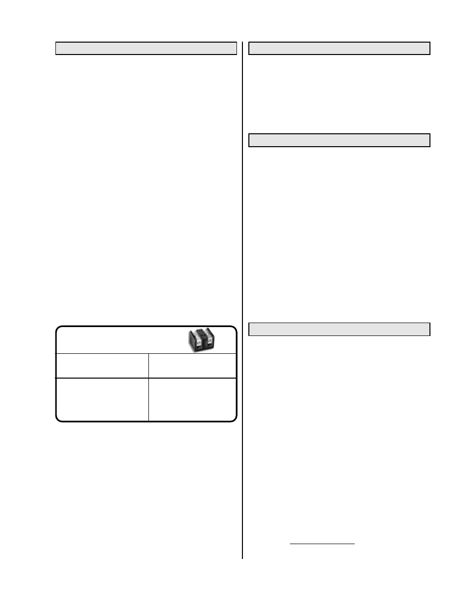
TORQUE TABLE FOR
USD CONNECTORS
10 -14 ga
35 in-lbs
8 ga
40 in-lbs
4 - 6 ga
45 in-lbs
2-3 ga
50 in-lbs
Wire Size
Recommended
Torque