Precision Control Systems 1032 User Manual
Page 3
Model 1032
1 of 9
Part No. 5000095-1011-6 6/13/2003
The heart of the power controller is the SCR
(Silicon Controlled Rectifier, also sometimes re-
ferred to as a thyristor).
The SCR has two states, ON and OFF, and allows
current to flow in only one direction when turned
on. SCRs can remain in the off state even though
the applied potential may be several thousand
volts. In the on state, they can pass several thou-
sand amperes. When a small signal is applied
between the gate and cathode terminals, the SCR
will turn on within 10-100 microseconds. Once
turned on, it will remain on until the current through
it is reduced below a very low value, referred to as
the holding current. Since the SCR conducts in
only one direction, two are placed back to back in
an inverse parallel configuration to control AC
current. (Figure 1A.)
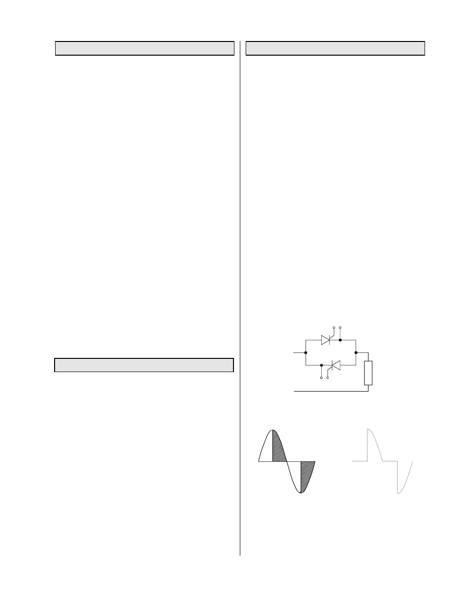
Phase-angle: In phase-angle control, each SCR
of the back-to-back pair is turned on for a variable
portion of the half-cycle that it conducts (Figure 1,
B&C). Power is regulated by advancing or delaying
the point at which the SCR is turned ON within
each half cycle. Light dimmers are an example of
phase-angle control.
Phase-angle control provides a very fine resolution
of power and is used to control fast responding
loads such as tungsten-filament lamps or loads in
which the resistance changes as a function of
temperature. Phase-angle control is required if the
load is transformer-coupled or inductive.
The model 1032 is a single-phase, phase-angle, SCR
power controller with features of field adjustable cur-
rent limiting, soft-start and missing cycle detection.
The controller can be ordered to accept command
signals of 0-10Vdc, 0 to 5Vdc, 1-5mA, 4-20mA, or a
potentiometer signal. Models are available for opera-
tion at 120, 208, 240, 377, 480 or 575Vac 50/60 hertz.
The controllers can be obtained with current ratings of
10, 20, 30, 40 or 70 Amps.
The model 1032 linearly controls, with respect to the
command signal, the RMS value of the voltage applied
to the load. The controller also has line voltage
compensation, which, for a constant command sig-
nal, maintains the load voltage constant, independent
of line or supply voltage variations.
The soft-start and missing cycle detection features
set the load voltage to zero on power interruptions of
one half cycle or more, and then increases the load
voltage to the desired value at a predetermined rate.
This feature, on start up or after power failures,
prevents saturation of load transformers. The feature
also eliminates in-rush currents that can occur, due to
loads with a low cold resistance.
Current limiting allows the user to adjust the maxi-
mum current the controller will apply to the load. This
feature is desired when controlling loads such as
silicon carbide, molybdenum disilicide, or other ma-
terials in which the resistance changes with tempera-
ture and/or time.
Electrical isolation of the circuit card and the heat
sink is achieved by the use of an SCR that electrically
isolates the SCRs from its mounting plate, and which
uses photo couplers to isolate the SCR gate signals.
THEORY OF OPERATION:
DESCRIPTION:
MODEL No. IDENTIFICATION:
MODEL NUMBER: 1032-VV-AA-CS(-ILXX)
VV = Rated voltage
12 = 120Vac
24 = 240Vac (For 208 or 220 specify SC208 or
SC220)
48 = 480Vac (for 377 specify SC38)
57 = 575Vac
AA = Rated current capacity 10, 20, 30, 40 or 70 A
CS = Command Signal; The standard controller accepts
a 0 to 5Vdc, a 0 to 10Vdc, or a potentiometer signal.
If the controller has been supplied as a 4/20mA input, a
-4/20mA designator will be included in the model
number. An appropriate shunt resistor will be added to
the circuit to provide proper scaling. Check with factory
for other mA input ranges.
The term ILXX added to the model number implies that
the current limit will be factory adjusted for the value
specified by XX. When the ILXX term is not included,
the current limit will be factory set at 105% of the rated
current.
L
O
A
D
Figure 1A. Simplified diagram of an SCR controller
Figure 1B. SCR "ON"
time, shown by shaded
area, is varied to apply
the desired load
voltage.
Figure 1C. Voltage
waveform, as applied
to load.