Oem 1b, Circuit diagram pin functions – Martel Electronics OEM1B User Manual
Page 3
Page 2 of 4
Page 2 of 4
Page 3 of 4
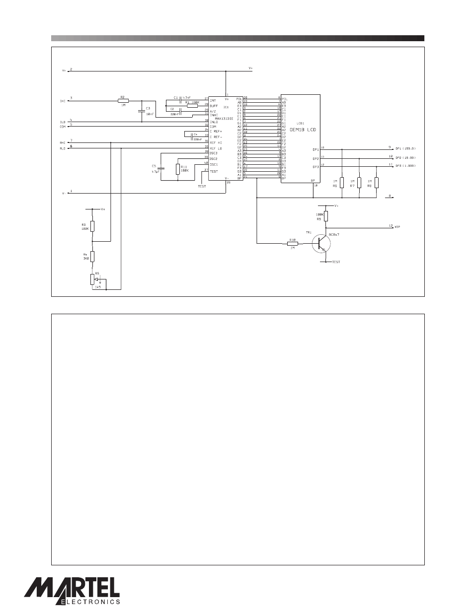
OEM 1B
3½ Digit LCD Voltmeter Module
CIRCUIT DIAGRAM
PIN FUNCTIONS
1.
V-
Negative power supply to the meter.
2.
V+
Positive power supply to the meter.
3.
IHI
Positive measuring input.
IHI must be no closer than 1.6V to either the positive or negative supply, when using the
internal 100mV reference.
4.
ILO
Negative measuring input.
ILO must be no closer than 1.6V to either the positive or negative supply, when using the
internal 100mV reference.
5.
COM
6.
RLO
Negative input for the reference voltage.
7.
RHI
Positive input for the reference voltage.
8.
NC
Do not connect.
9.
DP1
Connect to XDP to display DP1 (199.9).
10.
DP2
Connect to XDP to display DP2 (19.99).
11.
DP3
Connect to XDP to display DP3 (1.999).
12.
XDP
Connect to DP1, DP2 or DP3 to display required decimal points.
Ground for the analogue section of the A/D converter. It is actively held at 3.05V (nom.) below
V+ and must not be allowed to sink excessive current (>100mA) by, for instance, connecting
to a higher voltage.
www.lascarelectronics.com
NC
PO Box 770, Londonderry, NH 03053 1-800-821-0023
www.martelcorp.com
page 3 of 4