Dpm 750s-bl, Pin functions solder links, Circuit diagram – Martel Electronics DPM750S-BL User Manual
Page 3: 3½ digit backlit lcd voltmeter module
Page 3 of 4
DPM 750S-BL
3½ Digit Backlit LCD Voltmeter Module
PIN FUNCTIONS
SOLDER LINKS
1.
V+
Positive power supply to the meter and LED backlighting.
2.
GND
0V power supply to the meter.
4.
INHI
Positive measuring input.
5.
INLO
Negative measuring input.
6.
DP1
Connect to V+ to display DP1 (199.9).
7.
DP2
Connect to V+ to display DP2 (19.99).
8.
DP3
Connect to V+ to display DP3 (1.999).
9.
V-
Negative power supply to the meter.
10.
COM
Ground for analogue section of A/D converter.
It is actively held at 3.05V (nom.) below V+ and must not be allowed to sink excessive
current (>100 A) by, for instance, connecting to a higher voltage.
A negative supply is generated internally and mirrors the positive supply. For example: if V+ is +5V, then the
internally generated V- is -5V. When measuring with the input referenced to the same supply rail as that of the panel
meter, then the limitations on the input range are (V- + 1.5V) to (V+ - 1.5V).
LCOM
Normally Open.
When soldered, connects COM to INLO.
La
Normally Closed. Short circuits the scaling resistor Ra.
µ
Note:
3.
BL-
Negative power supply connection to the LED backlighting.
www.lascarelectronics.com
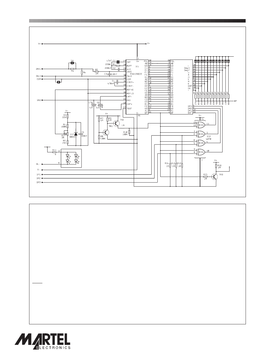
CIRCUIT DIAGRAM
V+
XDP
XDP
1
4
5
10
2
3
33
9
6
7
8
LCOM
LCD 600
BC847
BC847
BC847
PO Box 770, Londonderry, NH 03053 1-800-821-0023
www.martelcorp.com
page 3 of 4