Mpp- 24-m, Panelpilot compatible smart graphics display, Hardware – Martel Electronics MPP-24-M User Manual
Page 2
PanelPilot Compatible Smart Graphics Display
The input voltage range is decided using the two voltages that the user enters in the
scaling section of the Panel Pilot software. The software uses the smallest range
available, which can accommodate both of the voltages entered by the user. The
absolute maximum voltage input is 40V d.c.
For example:
Entering a voltage scale of 0 – 30V in the software will use the 0 – 40V range.
Entering a voltage scale of 0 – 3V in the software will use the 0 – 4V range.
Entering a voltage scale of 5 – 15V in the software will use the 0 – 20V range.
HARDWARE
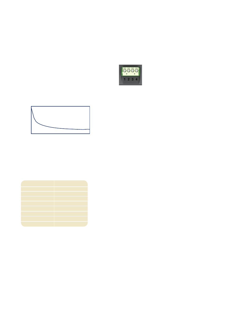
Screw Terminal Functions
1 IN2 Analogue voltage input 2 (maximum of 40V d.c.)
2 IN1 Analogue voltage input 1 (maximum of 40V d.c.)
3 0V 0V power supply input
4 V+ Positive power supply input (4V – 30V d.c.)
0
100
200
4
17
30
Current
(mA)
Voltage (V)
Typical Supply Current
Voltage Range (V)
0 - 1.25
0 - 2.5
0 - 4
0 - 5
0 - 8
0 - 10
0 - 20
0 - 40
Resolution (mV)
4.9
2.4
2.0
1.2
1.0
0.3
9.8
0.6
www.lascarelectronics.com
USB connection
Note: V+, IN1 and IN2 share a common ground (i.e. not floating or isolated from each other).
MPP-
24-M
available resolution(the smallest voltage range offers the highest resolution). Each channel can be programmed independently, with
the option of eight different input voltage ranges:
A‘Type A to Mini-B’ USB cable is required to program and customise the MPP-24-M. It typically takes10 seconds to send a
configuration, with an additional 5 seconds needed for the hardware to reset.
The MPP 24-M can be powered directly from USB and is compatible with both USB 1.1 and USB 2.0. The screw terminals and
advancedconnector can remain connected while still using USB, but it is not necessary for V+ to be powered.
Voltage Input The MPP-24-M features 2 voltage inputs, which use aProgrammable GainAmplifier (PGA) to make the best use of