Pin functions, Circuit diagram, 3½ digit lcd voltmeter module – Martel Electronics V1 User Manual
Page 3: Solder links
PIN FUNCTIONS
1.
V+
Positive power supply connection.
2.
V-
Negative power supply connection.
3.
INHI
Positive measuring input with reference to IN LO.
4.
INLO
Negative measuring input with reference to IN HI.
5.
XDP
Connect to DP1, 2 or 3 to display required decimal point.
6.
DP1
Connect to XDP to display Decimal Point 1 (199.9).
7.
DP2
Connect to XDP to display Decimal Point 2 (19.99).
8.
DP3
Connect to XDP to display Decimal Point 3 (1.999).
L1
Normally Closed, connects COM to INLO.
Solder Links:
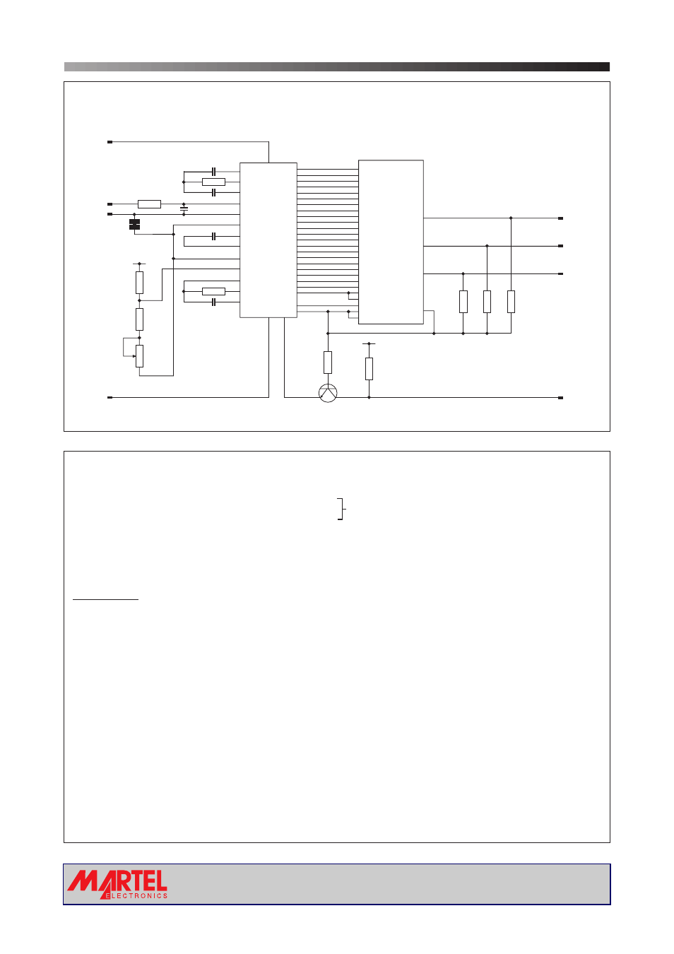
CIRCUIT DIAGRAM
V 1
3½ Digit LCD Voltmeter Module
Analogue inputs must be no closer than 1V
to either the positive or negative supply.
V+
1
6
7
8
5
3
4
2
V+
V+
INHI
INLO
V-
L1
DP1
DP2
DP3
XDP
INT
V+
V- TEST
27
1
26
28
29
31
30
32
34
39
40
38
33
DP1
LOBAT
199.9
DP2
19.99
DP3
1.999
BUF
A/Z
IN HI
IN LO
COM
CREF+
CREF-
36
REF HI
35
REF LO
OSC1
OSC2
OSC3
IC1
LCD1
R9
1M
R6
100k
R11
100k
R10
100k
Q1
3904
R3 100k
C5
100pF
C4
100nF
C1
100nF
R1
180k
R2
1M
C2
220nF
C3
100nF
R5
3k
R4
1.5k
R8
1M
R7
1M
8
6
3
28
a1
a1
d1
d1
e1
e1
f1
f1
g1
g1
f2
f2
a2
a2
g2
g2
e3
e3
b2
b2
a3
a3
f3
f3
c2
c2
b3
b3
g3
g3
d2
d2
c3
c3
bc4
b4
c4
e2
e2
d3
d3
b1
b1
c1
c1
5
12
2
9
8
15
6
13
7
14
13
20
12
19
25
7
18
4
11
18
23
24
17
25
10
17
16
23
22
2
26
27
30
9
16
24
5
19
14
21
15
22
4
11
3
10
37
POL
POL
BP
COM
COM
20
29
21
1
www.martelmeters.com
page 3 of 4