Various operating modes, Pin functions – Martel Electronics DPM500 User Manual
Page 2
Specifications liable to change without prior warning
DPM 500
Issue 4
July/1999
M.C.
Applies to DPM 500/7
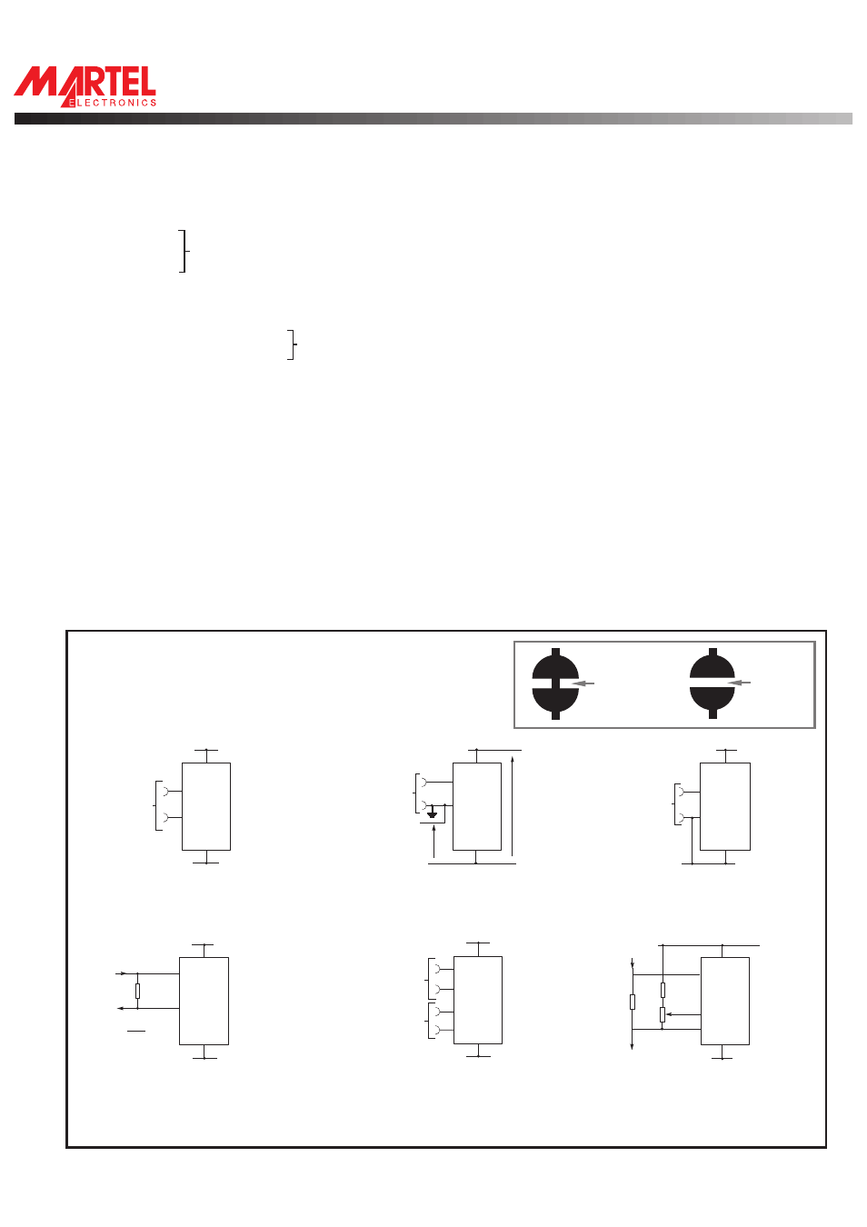
Links 1, 2, 3, 4 SHORTED.
VARIOUS OPERATING MODES
ON-BOARD LINKS: In order to quickly and easily change operating modes for
different applications, the meter has several "on-board links". They are designed
to be easily opened(cut) or shorted (soldered).
Do not connect more than one meter to the same power supply if the meters cannot
use the same signal ground. Taking any input beyond the power supply rails will
damage the meter.
Normally
SHORTED
Cut to
OPEN
Normally
OPEN
Solder to
SHORT
V+
V+
1
30
31
IN HI
IN LO
26
V-
V-
+
-
±200mV
Links 1, 2, 3 & 4 SHORTED.
32
31
V-
V-
V+
V+
1
26
30
220K
5K
6R2
IN
HI
IN
LO
COM
Links 1, 3 & 4 SHORTED.
PIN FUNCTIONS
SPECIAL NOTE: ANNUNCIATORS.
SPECIAL NOTE: ANNUNCIATORS.
LED BACKLIT VERSIONS:
SPECIAL NOTE: ANNUNCIATORS:
1, 40. V+
Positive power supply.
2 -7, 12-14, 17, 38, 39 See
15. -
Input for the polarity annunciator. Internally linked to POL (pin 20). If this is to be externally controlled, cut link 11.
16, 18, 19, 22
XB3, E3, AB, XG3. Outputs for use in auto-ranging applications.
20. POL
Drive for "-" annunciator. Internally connected by link 11.
21. BP
LCD backplane drive waveform.
23. DP3
1.999
24. DP2
19.99
See
25. DP1
199.9
26. V-
Negative power supply. Note that if the DPM 500S-BL is being used, the voltage between V+ and V- must not exceed 6.5V.
27. XDP
Connect to required annunciators/DPs (see note).
28. -5V
Output from negative rail generator circuit. This output is an inversion of V+ (DPM 500S BL ONLY).
29. BG
Input for bandgap reference. (1.22V nom).
30. IN LO
Negative measuring input. Analogue inputs must be no closer than 1V to either the positive or negative supply. The negative
31. IN HI
Positive measuring input.
supply of the DPM 500S-BL is generated internally and mirrors the positive supply voltage.
32. COM
The ground for the analogue section of the A/D converter, held actively at 2.8V (nom) below V+. COM must not be allowed to sink
excessive current (> 100 A) by connecting it directly to a higher voltage.
33. REF-
Negative output from internal reference.
34. REF+
Positive output from internal reference.
35. REF LO
Negative input for reference voltage.
36. REF HI
Positive input for reference voltage.
37. TEST
Connecting this pin to V+ turns on the segments as illustrated. It should not be operated for more than a few seconds as the DC
voltage applied to the LCD may "burn" the display. This pin is nominally at 5V below V+ and is the ground for the digital section
of the meter, it can be used as a negative supply to power external logic up to a maximum of 1mA.
40. V+/CLK Normally tied to V+ via Link 12 but can be used to over ride the internal oscillator and control the sample rate by cutting Link 12 and
making Link 13.
Apply 5V DC to the backlight tab on the side of the meter. Typical current is 30mA. For higher voltages, fit a resistor in series.
E.g. For 9V use 150R. Maximum current = 60mA.
The DPM annunciators (DPs, °C, etc.) can be displayed by connecting them to XDP. However as these
annunciators are normally ‘floating’, under certain conditions they may appear when not wanted. To suppress unwanted annunciators, link them to
the backplane (BP). If the annunciators are being switched, connect them via a 1M resistor to the BP (pin 21). The annunciators will then operate
normally when connected to XDP. Ensure that an annunciator is not connected directly to the XDP and BP at the same time.
µ
V-
V+
30
31
26
1
I
IN
I
OUT
R
IN HI
IN LO
R= 0.2
I
FSR
V-
V+
30
+
+
-
-
V
2
V
1
31
REF HI
IN HI
IN LO
REF LO
1
35
26
V-
V-
36
V+
V+
V+
+
-
V+
IN
HI
IN
LO
0V
±200mV
30
31
26
1
Links 1, 3 & 4 SHORTED.
V-
±200mV
V+
V+
1
26
-
+
0V
1V min
V-
14V max
7V min
31
30
V-
IN LO
IN HI
Links 1, 3 & 4 SHORTED.
Measuring a floating voltage
source of 200mV full scale.
Measuring current
(supply MUST be isolated).
Measuring a single ended input
referenced to supply (DPM 500S-BL).
Split supply operation (DPM 500).
Measuring the ratio of two voltages.
Reading = 1000 V /V
50mV< V <200mV
V <2V .
1
2
2
1
2
Measuring 4-20mA to read 0-999
(supply must be isolated).
Martel Electronics, Corp. P.O. Box 770 Londonderry, NH 03053
Toll Free: (800) 821-0023 Phone: (603) 434-1433 Fax: (603) 434-1653