Sp 100, Pin functions, Circuit diagram – Martel Electronics SP100 User Manual
Page 3: 3½ digit led voltmeter module
PIN FUNCTIONS
1.
V+
Positive power supply to the meter.
2.
DE
Display Enable. Connect to V+ for normal operation.
Do not connect to enter low power mode. The display is then blanked, but the voltmeter section
continues to operate. In low power mode, the current consumption is reduced to 400 A (typ).
3.
0V
0V power supply connection to the meter.
4.
DP3
Connect to 0V to display DP3 (199.9).
5.
DP2
Connect to 0V to display DP2 (19.99).
6.
DP1
Connect to 0V to display DP1 (1.999).
7.
R I
Reference voltage input for the meter's A/D converter.
8.
RO
Precision reference voltage output. Connect to RI for normal operation.
9.
T
Connect to V+ to test the display. All segments will be displayed, except for decimal points.
10. COM Ground for analogue section of A/D converter.
It is actively held at 3.05V (nom) below V+ and must not be allowed to sink excessive current
(>100 A) by, for instance, connecting to a higher voltage.
11. INH
Positive measuring input.
12. INL
Negative measuring input.
A negative supply is generated internally and mirrors the positive supply. For example: if V+ is +5V, then
the internally generated V- is -5V. When measuring with the input referenced to the same supply rail as
that of the panel meter, then the limitations on the input range are (V- + 1.5V) to (V+ - 1.5V).
µ
µ
Note:
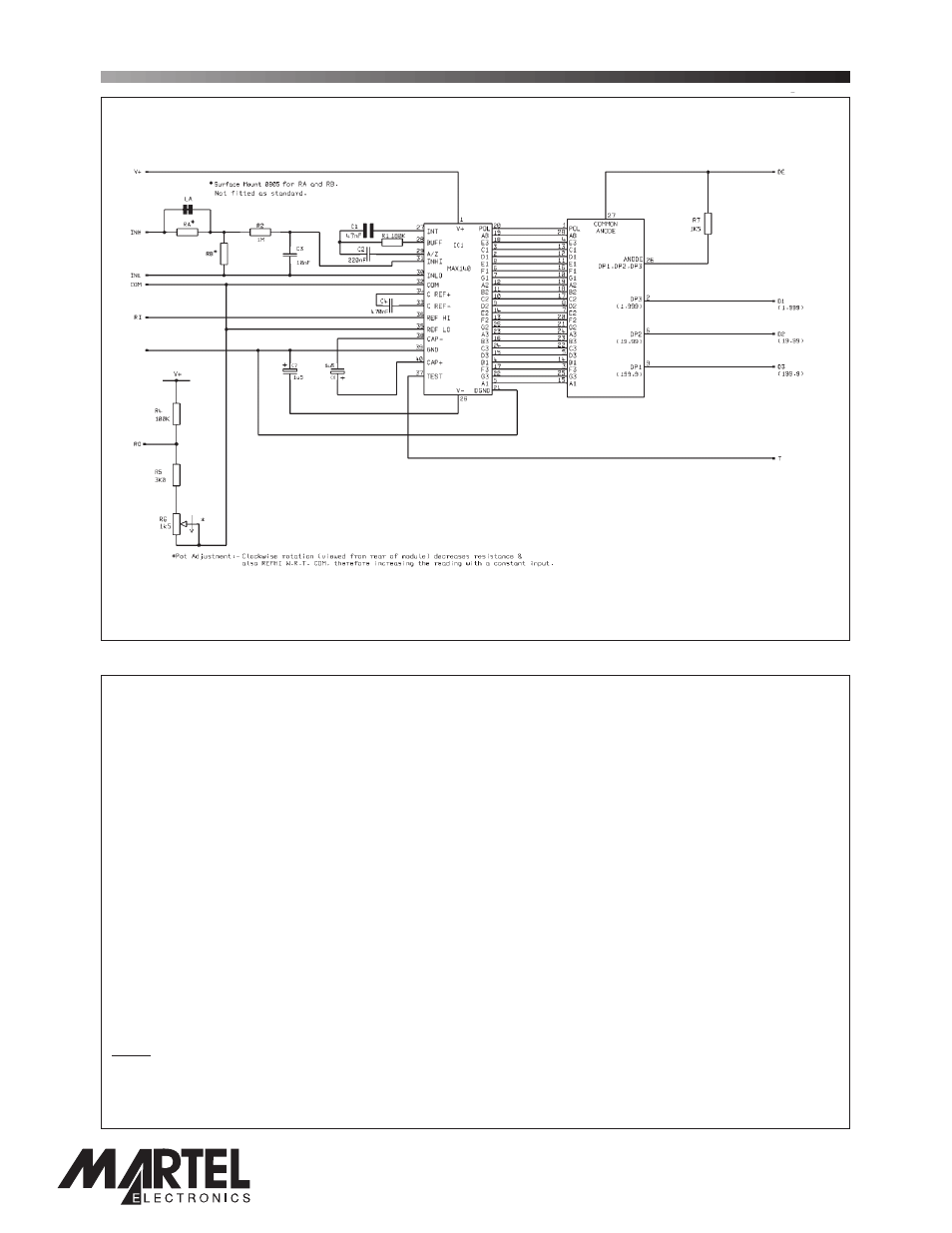
CIRCUIT DIAGRAM
Page 3 of 4
SP 100
3½ Digit LED Voltmeter Module
1
11
12
10
7
3
8
0V
2
6
5
4
9
www.lascarelectronics.com
PO Box 770, Londonderry, NH 03053 1-800-821-0023
www.martelcorp.com