Screw terminal functions, Applications, Scaling – Martel Electronics SP5-1200-BL User Manual
Page 3: Wire signal-powered meter
SCREW TERMINAL FUNCTIONS
V+
Positive power supply to the meter / voltage being measured.
0V
0V power supply to the meter / voltage being measured.
BL+
Positive power supply to the LED backlighting.
BL-
Negative power supply to the LED backlighting.
When the jumper link is placed over both pins, located next to the screw terminals, this connects the 0V of the LED
backlighting to the 0V of the signal being measured. This allows for 3-wire operation of the module.
This connection should only be made if both power supplies can share a common 0V line.
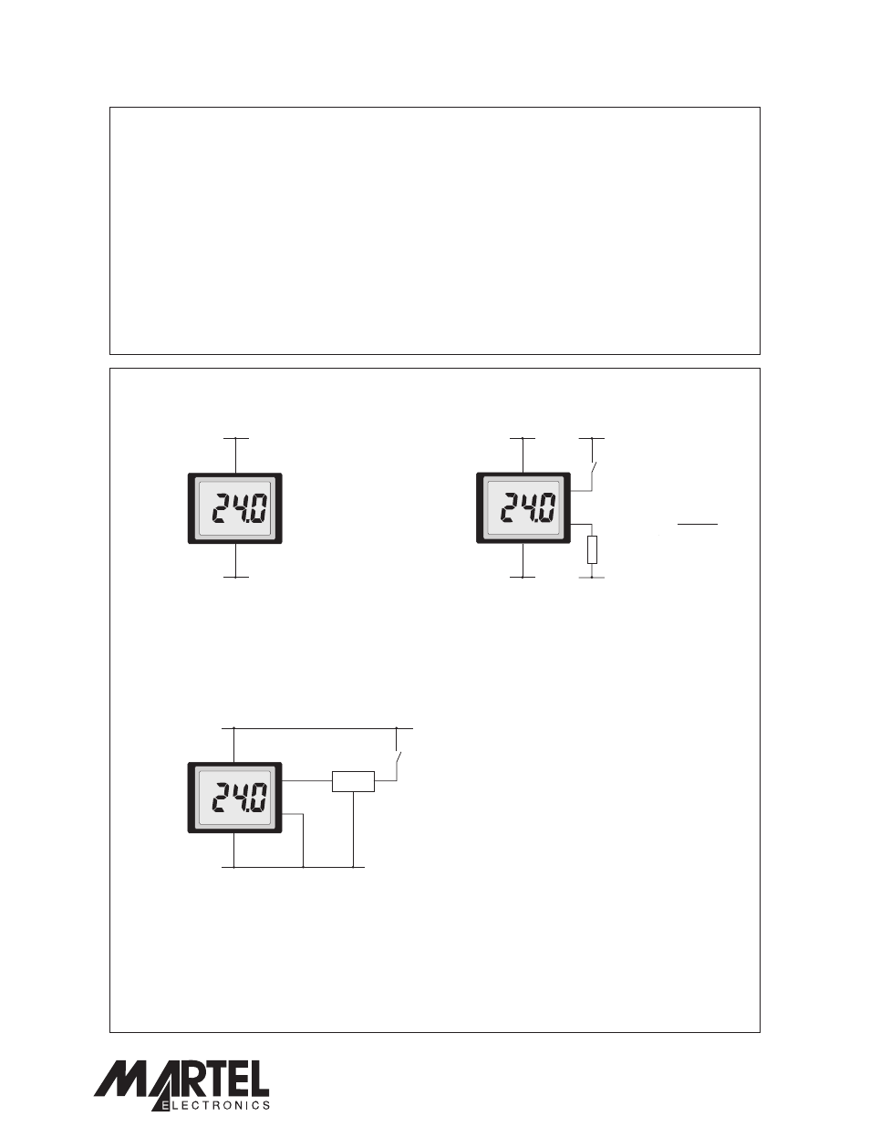
APPLICATIONS
Measuring a voltage in the range 4 to 25V d.c.
+4 to +25Vd.c.
+4 to +25Vd.c.
0V
0V
V+
V+
0V
0V
Powering the LED backlighting from a separate supply.
Close switch S1 to turn on the backlighting.
Note: - add a series resistor R if the backlighting
supply voltage is higher than 5V d.c.
V
BL
BL+
BL-
0V
S1
R =
0.05
R is not needed
if VBL=5V (then
connect BL- to 0V)
VBL - 5V
R
SCALING
This module cannot be re-scaled for other voltage or current scales.
Specifications liable to change without prior warning
SP 5-1200-BL
Issue 4
November/2003
M.C.
Applies to SP 5-1200/2
Page 3 of 3
www.lascarelectronics.com
SP 5-1200-BL
2-Wire Signal-Powered Meter
Powering the LED backlighting from the voltage being
measured. The additional load of the backlighting on the
may cause this voltage to drop.
The voltage regulator may require a heatsink to limit its
temperature rise. Ensure that the maximum input specification
of the voltage regulator considerable exceeds the maximum
peak voltage that can be experienced on the supply line being
monitored.
voltage being measured
+7.5 to +25Vd.c.
0V
V+
0V
BL+
BL-
7805*
I/P
O/P
S1
* High input
voltage version
PO Box 770, Londonderry, NH 03053 1-800-821-0023
www.martelcorp.com