Various operating modes, Scaling, Power supply – Martel Electronics SP5-1710-BL User Manual
Page 4: Battery, 17 segment analogue lcd meter, Page 4 of 4
+
-
Ra
Rb
Voltage
Ra=1M
Rb=Ra.
V1-V2
V2
.
+
-
Rb
Load
I
FSD
Current
Rb=
I
1V
FSD
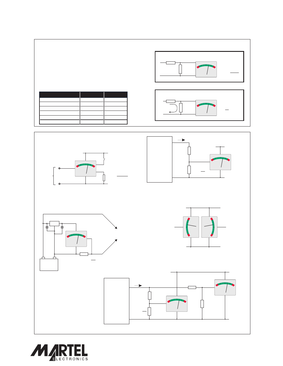
Required F.S.R.
Ra
Rb
10V
910k
100k
100V
1M
10k
1mA
0R
1000R
10mA
0R
100R
100mA
0R
10R
1A
0R
1R
Specifications liable to change without prior warning
SP 5-1710-BL
Issue 1
January/2004
M.C.
Applies to SP 5-1710/2
Page 4 of 4
www.lascarelectronics.com
VARIOUS OPERATING MODES
Indicating a d.c. current.
Indicating 2 voltages
Rb =
I
1V
Rb =
I
1V
5...12Vd.c.
0V
Load
Power
Supply
Indicating a voltage in the range 0 to 1V d.c.
Close switch S1 to turn on the backlighting.
Jumper link JBL must NOT be fitted.
J1 not fitted
J2 not fitted
J3 not fitted
J4 not fitted
J1 not fitted
J2 not fitted
J3 not fitted
J4 not fitted
J1 not fitted
J2 not fitted
J3 not fitted
J4 not fitted
J1 not fitted
J2 not fitted
J3 not fitted
J4 not fitted
J1 fitted
J2 not fitted
J3 fitted
J4 fitted
J1 not fitted
J2 not fitted
J3 not fitted
J4 not fitted
J1 not fitted
J2 fitted
J3 not fitted
J4 not fitted
0-1Vd.c.
5...12Vd.c.
+
-
0V
I
SCALING
Two external resistors may be used to alter the
full scale reading of the meter - see table for
sample values.
Alternatively, use the
following formulae to calculate Ra and Rb.
Select the nearest available standard resistor.
To achieve optimum accuracy, use 1% metal
film resistors. Ensure solder link La is cut
when fitting Ra.
S1
R =
0.05
V+ - 5V
R
V2
Vin
Vin
0V
0V
V2
Simultaneous d.c. Voltage and Current Indication.
R
=
I
b2
1V
5...12Vd.c.
0V
Load
Rb1
Ra1
Power
Supply
I
Current
Voltage
Indicating battery
charge/discharge current.
Ensure jumper link LK1 is fitted.
+
-
7805
Battery
To charger / load circuit
0
-
+
5...12Vd.c.
Vin1
Vin2
0V
SP 5-1710-BL
17 Segment Analogue LCD Meter
V+
0V
Vin
V+
0V
Vin
BL+
BL-
V+
V+
V+
0V
0V
0V
Vin
V+
0V
Vin
V+
0V
Vin
Vin
Vin
PO Box 770, Londonderry, NH 03053 1-800-821-0023
www.martelcorp.com