Audiovox PRO 9171FT User Manual
Page 2
The PRO-9171FT is for Automatic Transmission vehicles only! Although it is a sophisticated system, with
multiple built-in safety features, it must not be installed into vehicles with manual transmissions. Doing this can
cause serious personal injury and property damage.
IMPORTANT ! DO NOT PLUG THE SIX PIN MAIN POWER HARNESS OR THE 12 PIN INPUT / OUTPUT
HARNESS INTO THE REMOTE START CONTROL MODULE UNTIL ALL CONNECTIONS
HAVE BEEN MADE TO THE VEHICLE. AFTER SELECTING YOUR TARGET WIRES AS
DEFINED BELOW DISCONNECT THE NEGATIVE BATTERY CABLE FROM THE BATTERY
PRIOR TO MAKING ANY CONNECTIONS!
WIRING CONNECTIONS: 6 Pin Main Power Harness
RED w/ WHITE Tracer Wire : + 12 VDC Battery 1 Source
Connect this wire to a +12 VDC constant source found at the vehicles ignition switch using the 30 A fuse provided.
The Battery 1 source provides +12 volts to the PRO-9171FT module for Ignition 1 output, Ignition 2 output, and
the circuits logic.
RED Wire : + 12 VDC Battery 2 Source
Connect this wire to a + 12 VDC constant source found at the vehicles ignition switch but NOT the same wire
as the battery 1 source. Most vehicles have multiple +12 VDC battery feeds found at the vehicles ignition switch.
Separate feed wires must be used for the red and red w/white wires. If your vehicle does not provide at least two
+12 VDC feed wires, then it is possible to connect both wires to the vehicle battery. If connecting to the vehicle
battery always fuse these wires at the source using the 30 A fuses provided.
The Battery 2 source provides + 12 volts to the PRO-9171FT module for Starter output and Accessory output.
YELLOW Wire : Starter Output
Connect this wire to the starter wire from the ignition switch harness. This wire will show +12 Volts when the
ignition key is turned to the “ START or CRANK “ position, and 0 Volts when the ignition key is in any other
position.
NOTE: If installing the PRO-9171FT with an alarm that utilizes a starter cut relay, make sure the Yellow wire
is connected to the “ starter “ side of the relay contacts, and not the “ switch “ side.
When installing the PRO- 9171FT into vehicles with a factory installed security system, connect the Yellow wire
between the output of the starter cut relay and the neutral safety switch.
BLUE Wire : Ignition 1 Output
Connect this wire to the ignition 1 wire from the ignition switch harness. This wire will show +12 Volts when the
ignition key is turned to the “ RUN or ON “ and the “ START or CRANK “ positions, and 0 Volts when the key
is turned to the “ OFF “ and “ ACCESSORY “ positions.
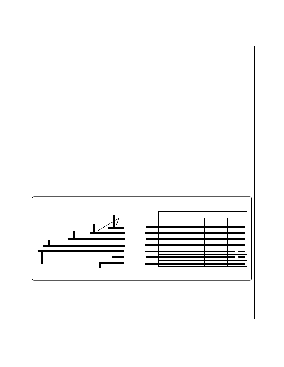
BATT 1
BATT 2
ACC
IGN 1
IGN 2
IGN 3
START
*
IGNITION SWITCH KEY POSITION
OFF
ACCESSORY
ON / RUN
START
SEE"WIRINGTHE12PINCONNECTOR"-
LT.BLUEWIREIFREQUIRED.
LT. GREEN WIRE
FROM PRO 9171FT
YELLOW WIRE
FROM PRO 9171FT
+12 VDC IN KEY POSITION INDICATED
MAY BE +12 VDC IN KEY POSITION INDICATED
*
THISCIRCUITISNOTALWAYSREQUIREDFORINSTALLATION
WIRING THE 6 PIN MAIN POWER HARNESS
LT. BLUE WIRE
FROM PRO 9171FT
VIOLET WIRE
FROM PRO 9171FT
RED w/WHITE TRACE
WIRE FROM PRO 9171FT
RED WIRE
FROM PRO 9171FT
SPLICE(TYP.)