KYORITSU 6201 User Manual
Page 20
―
18
―
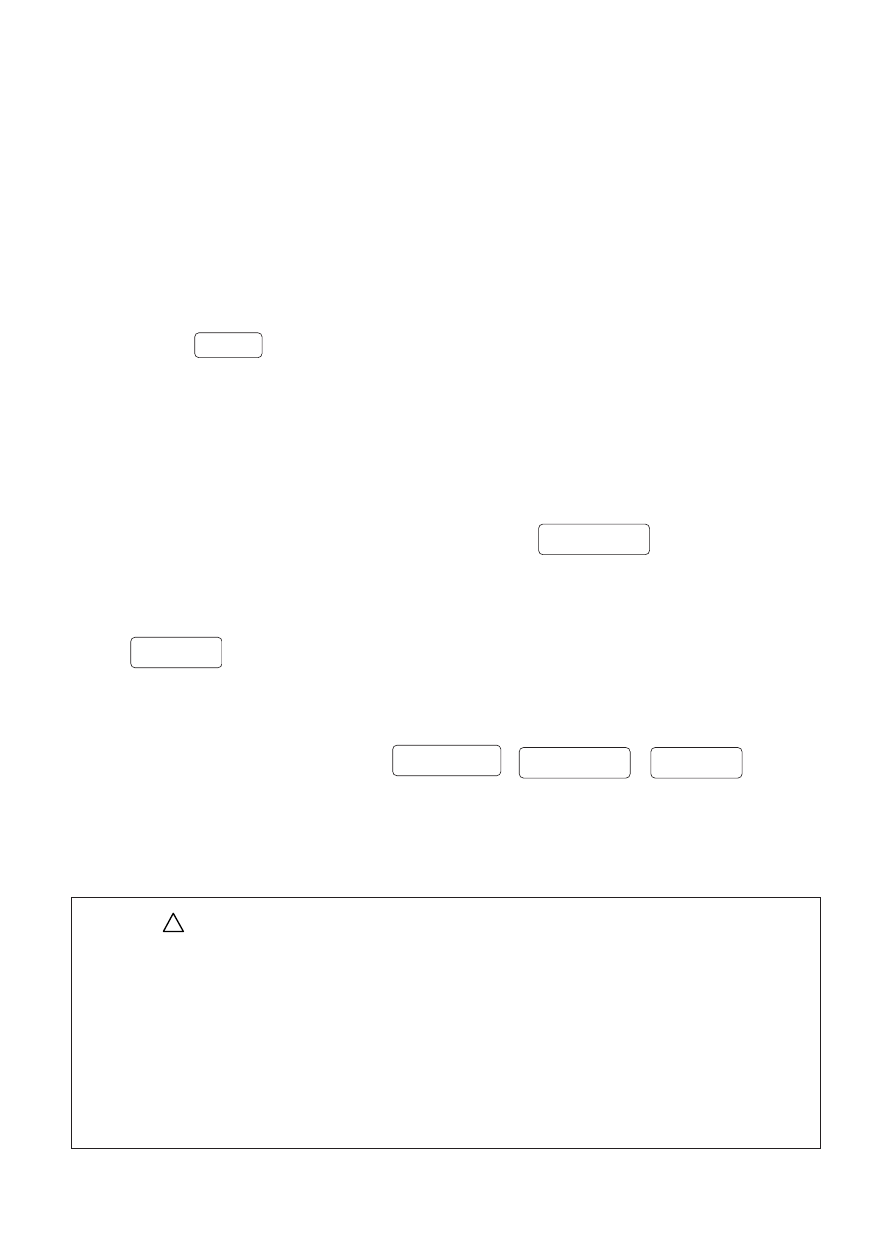
(1) Plug the extension leads adaptor M-7140 to the IEC socket of
M-6201 connector block.
(2) Connect the plug of the adaptor M-7140 for extension lead with the
connector of the extension lead.
(3) Insert the plug of extension lead into the socket on the front side of M-6201.
(4) Set the range switch on M-6201 to Extension Leads Test range, and
press the
START
switch.
(5) Then protective conductor resistance is measured.
When it passes(1
Ω
or less),lights up in green and display the measured
result on the LCD.
(6) Then the instrument automatically performs insulation resistance
measurement. When it passes(1M
Ω
or more),
lights up in green
and the measured result is displayed on the LCD.
(7) Polarity test will be performed the next, and when it passes,
lights up in green and the measured values of protective
conductor resistance and insulation resistance will be alternately displayed
on the LCD .
(8) When it fails at any of three:
, the
corresponding LED lights up in red and further measurement will be stopped.
The measured value, which is failed the test, and the message "no" will be
displayed on the LCD in turn.
CAUTION
●
Follow the procedure described in 5.2-3 and do NULL setting before a
measurement.
●
Alligator clip must make good contact with the enclosure of the DUT.
●
When the terminal is open or the resistance value exceeds measuring
range, "OL" mark (over range display) appears on the LCD.
●
Do not touch the device under test while testing is in progress.
Since a high voltage of 500V, user may get electrical shock.
!
○
Polarity
○
Polarity
Earth
○
Continuity
○
Insulation
○
Insulation