Device description, 8 electrical data – KROHNE H250 M40 NEPSI Ex ia User Manual
Page 14
2
DEVICE DESCRIPTION
14
H250 M40
www.krohne.com
03/2013 - 4002616701 AD H250 M40 NEPSI Ex ia R01 en
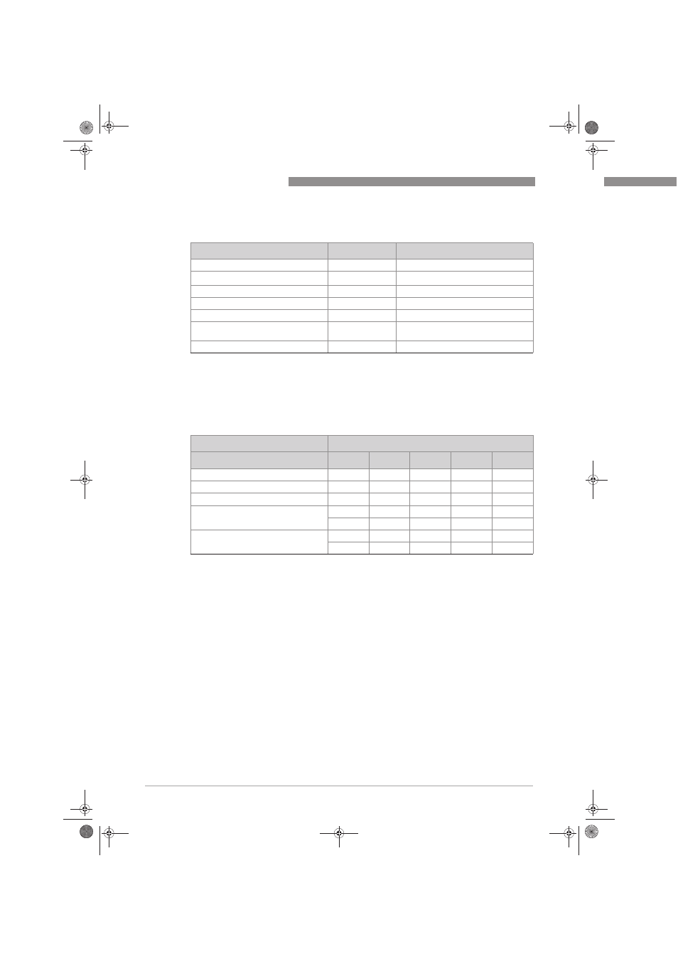
2.8 Electrical data
Built-in equipment for the variable area flowmeter may only be connected to separate
intrinsically safe circuits with the following maximum values:
Electrical equipment
Rated voltage
Nominal current
Limit switch K1 / K2
8 VDC
≤1 / ≥3 mA
Signal output ESK4
14 - 30 VDC
4...20mA with HART
®
communication
Switching output ESK4-T OC output
8 - 30 VDC
1...100 mA
Switching output ESK4-T NAMUR output 8 VDC
≤1 / ≥3 mA
Signal input ESK4-T input
8 - 30 VDC
≤2 mA
ESK4-FF Foundation Fieldbus
transmitter
1
9 - 30 VDC
16 mA
ESK4-PA Profibus transmitter
2
9 - 30 VDC
16 mA
1 Further information and instructions for operation of the ESK4-FF transmitter are provided in separate supplementary
instructions.
2 Further information and instructions for operation of the ESK4-PA Profibus transmitter are provided in separate sup-
plementary instructions.
Maximum values
Built-in equipment
U
i
[V]
Ii[mA]
P
i
[mW]
C
i
[nF]
L
i
[μH]
ESK4
30
130
1000
~ 0
10
ESK4-T (I/O-modul)
30
130
1000
10
~ 0
ESK4-PA / ESK4 FF
1
24
380
5320
~ 0
~ 0
I7S23,5-N / SC3,5-N0-Y
16
25
64
150
150
16
52
169
150
150
SJ3,5-SN / SJ3,5-S1N
16
25
64
30
100
16
52
169
30
100
1 FISCO field device
AD_H250_M40_NEPSI_Ex_ia_R01_en_4002616701_PRT.book Page 14 Friday, March 8, 2013 11:14 AM