Status output (1) namur b, Binary output 1) o/c-pnp b, Status output (2) namur b – KROHNE M10 Converter H250-H 54 Ex II2G EN User Manual
Page 8: Binary output 2) o/c-pnp b, Status input (reset counter) r
Signal converter M10-EEx d – Supplementary instructions
11/2002
8
•
Connect the shields by the shortest possible route to the press-fitted U-clamp terminal (PE) in
the terminal compartment. If shields are to be grounded at both ends (e.g. for EMC reasons),
adequate equipotential bonding is required between the two shield ends to avoid
unacceptable equalizing currents.
•
The signal converter must be incorporated in the equipotential bonding system of the
hazardous area. The cable is to be connected to the outer press-fitted U-clamp terminal in the
converter housing.
•
The measuring tube can be incorporated in the equipotential bonding system of the
hazardous area by means of the U-clamp terminal (if provided) in the flange or by means of
conductive connections (gaskets, etc.).
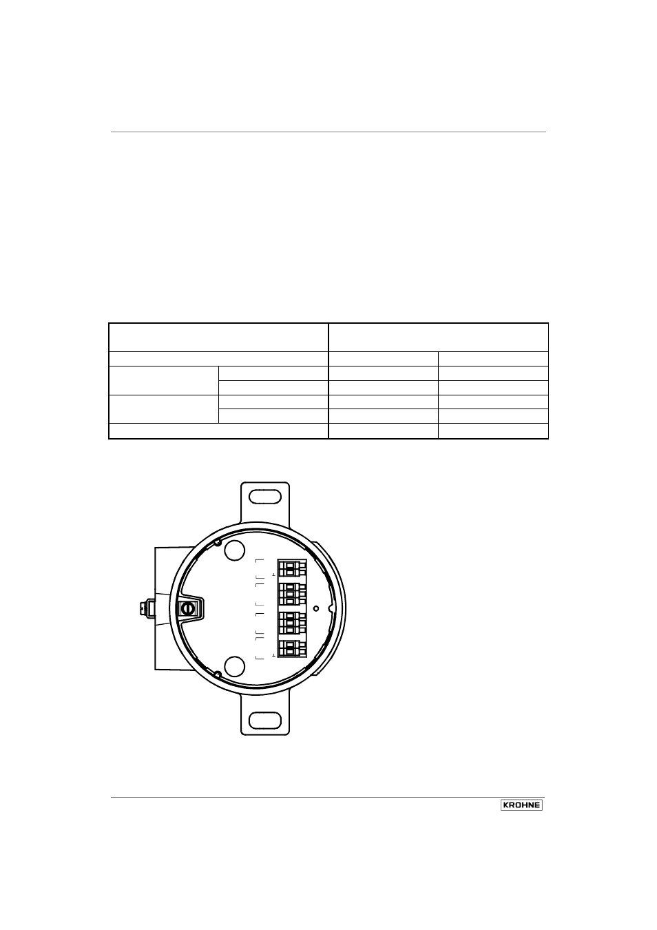
The terminal assignment is listed in the following table:
Function
Terminal
designation
Signal output
(see sketch)
Current output HART (current loop)
I
+
I
⊥
Status output (1)
NAMUR
B
+
B
N
(binary output 1)
O/C-PNP
B
+
B
OC
Status output (2)
NAMUR
B
+
B
N
(binary output 2)
O/C-PNP
B
+
B
OC
Status input (reset counter)
R
+
R
⊥
Note the electrical data of the circuits given in Section 3.7! Even when operated in the non-
hazardous area, the requirements pertaining to the signal output circuits need to be met.
R
+
R
B
N
B
OC
B
+
I
+
I
B
N
B
OC
B
+
A
ch
tun
g!
N
u
r be
sc
he
in
ig
te
Le
itu
ngs
ei
nf
üh
ru
ng
en
b
zw
.
Ro
hr
le
itu
ng
sad
ap
te
r v
er
w
en
de
n.
CA
UT
IO
N!
AP
PL
Y C
E
R
T
IF
IE
D
C
A
B
LE
EN
T
R
IE
S
O
R
CO
ND
UI
T
A
D
A
P
T
O
RS
O
N
LY
.
Cu
rr
e
nt
lo
op
Bi
na
ry
ou
tp
u
t 1
Bi
na
ry
ou
tp
ut
2
Re
se
t
co
un
te
r