KROHNE M10 Converter H250-H 54 Ex II2G EN User Manual
Page 5
11/2002
Signal converter M10-EEx d – Supplementary instructions
5
3.5
Cable entries / sealing plugs
Cable entries and sealing plugs must, in ready-to-operate condition, satisfy the IP Class of
Protection IP67 and each be separately certified in conformity with EN 50 018. Any requirements
specified in the test certificates of the components shall be observed.
3.6 Power
supply
Type H..../..../M10-EEx variable-area flowmeters do not require any separate power source. The
necessary supply is obtained via the current output.
3.7 I/O
functions
When connecting the I/O interfaces of the H..../..../M10-EEx variable-area flowmeters, the
following values need to be taken into account.
I/O function
(1)
Nominal values of the non-
Added restriction
certified receiver instrument
See Standard Installation
See Standard Installation
Supply power for receiver
and Operating Instructions
and Operating Instructions
instruments max. 253V
(1)
Only for connection to circuits with “functional extra-low voltage with protective separation
(PELV)”
Peak values U
AC
≤ 25V ; U
DC
≤ 60V
3.8
Ambient temperatures / temperature classes
The permissible ambient temperature for the variable-area flowmeters is limited to a value
of T
amb
≤ 60 °C.
With regard to maximum surface temperatures, variable-area flowmeters are exposed to three
heat sources:
•
Ambient temperature T
amb
•
Electric power loss P
v
•
Process temperature T
m
Accordingly, at a given maximum ambient temperature (T
amb
≤ 60°C) and a given maximum power
loss (P
v
≤ 3 W), we obtain maximum surface temperatures as a factor of the process temperature.
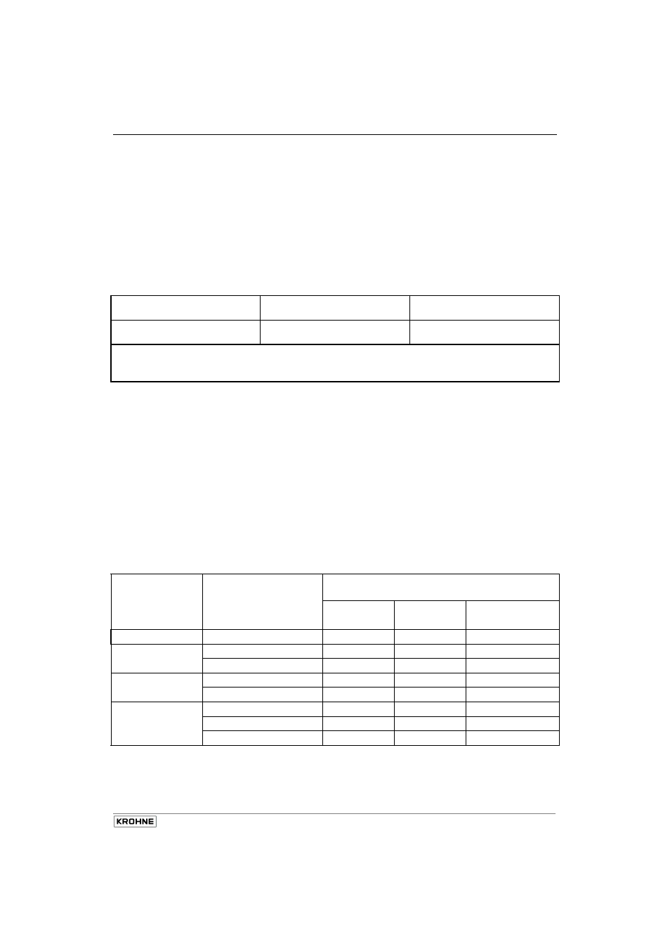
For that reason, the devices are not allocated to any specific temperature class; rather, the
temperature class of the devices is a function of the actual process temperature and ambient
temperature, see table below.
Temperature
class
Ambient temperature
in °C
Max. permissible process
permanent temperature
Wiring Wiring Wiring
70°C 80°C 90°C
T6
-40 … +60
85
85
85
T5
-40 … +50
100
100
100
-40 … +60
85
100
100
T4
-40 … +50
135
135
135
-40 … +60
85 135 135
T3 ... T1
-40 … +40
180 200 200
-40 … +50
135 190 200
-40 … +60
85 145 200
Table 1
Max. permissible process temperatures
The cable glands and line entries must have the same degree of thermal
stability as the connecting cable