Physikalisch-technische bundesanstalt – KROHNE M10 Converter H250-H 54 Ex II2G EN User Manual
Page 16
Signal converter M10-EEx d – Supplementary instructions
11/2002
16
Physikalisch-Technische Bundesanstalt
PTB
Brunswick and Berlin
Schedule to EC Type Test Certificate PTB 01 ATEX 1154
(17) Special
conditions
none.
Additional directions for safe operation
Connection conditions
1.
The H…./…./M10-EEx variable-area flowmeter shall be connected up via suitable
cable glands and/or conduit systems that satisfy the requirements of EN 50018
Sections 13.1 and 13.2 and for which a separate test certificate is to hand.
2.
Cable glands and entry fittings (screwed conduit entries) as well as blanking plugs
of simple design may not be used. On connection of the H…./…./M10-EEx
variable-area flowmeter using a conduit entry approved for the purpose, the
associated sealing facility must be arranged directly on the housing.
3.
Unused openings shall be closed off as defined in EN 50018 Section 11.9.
4.
The connecting cable of the variable-area flowmeter shall be permanently installed
and in such as manner as to be adequately protected against damage.
These directions shall in suitable form accompany each apparatus.
Equipotential bonding
The H…./…./M10-EEx variable-area flowmeter shall be incorporated in the local
equipotential bonding system.
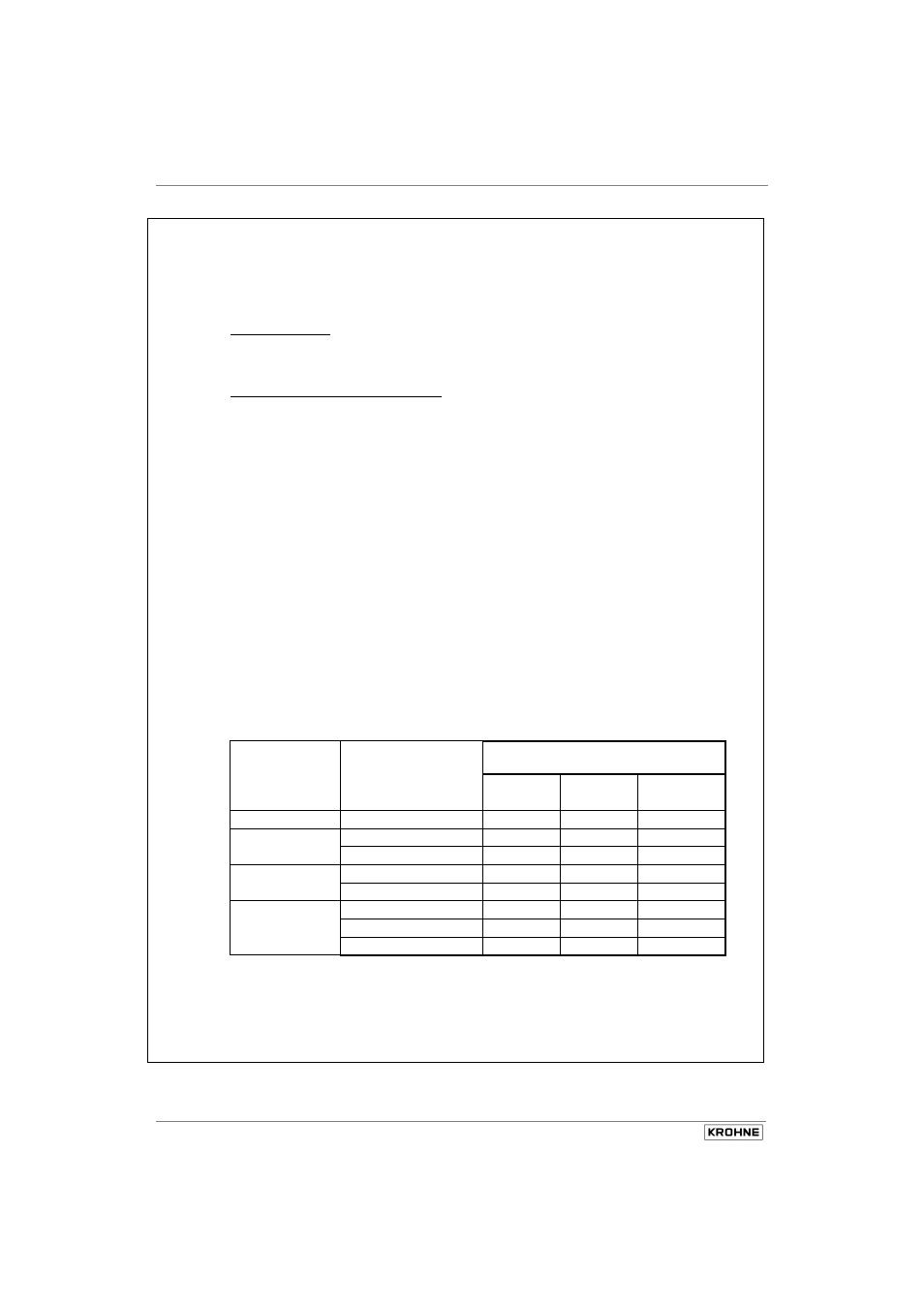
Permissible ambient and process temperatures as a factor of the temperature
class
Temperature
class
Ambient temperature in
°C
Max. permissible process
permanent temperature
Wiring Wiring Wiring
70°C 80°C 90°C
T6
-40 … +60
85
85
85
T5
-40 … +50
100
100
100
-40 … +60
85
100
100
T4
-40 … +50
135
135
135
-40 … +60
85 135 135
T3 ... T1
-40 … +40
180 200 200
-40 … +50
135 190 200
-40 … +60
85 145 200
The cable glands and line entries must have the same degree of thermal stability as the
connecting cable.
Page 3/4