Device description, 7 electrical data – KROHNE OPTIBAR PM 5060 C Ex d ia EN User Manual
Page 11
DEVICE DESCRIPTION
2
11
OPTIBAR 5060
www.krohne.com
07/2014 - 4003592001 - AD OPTIBAR 5060 Exd ia R01en
2.7 Electrical data
The metallic parts of OPTIBAR * 5060 VGK5/6/D*A/W E/Z/6/7 are electrically connected with the
ground terminals.
The supply and signal circuit is reliably galvanically isolated from parts which can be grounded.
OPTIBAR PM 5060 C
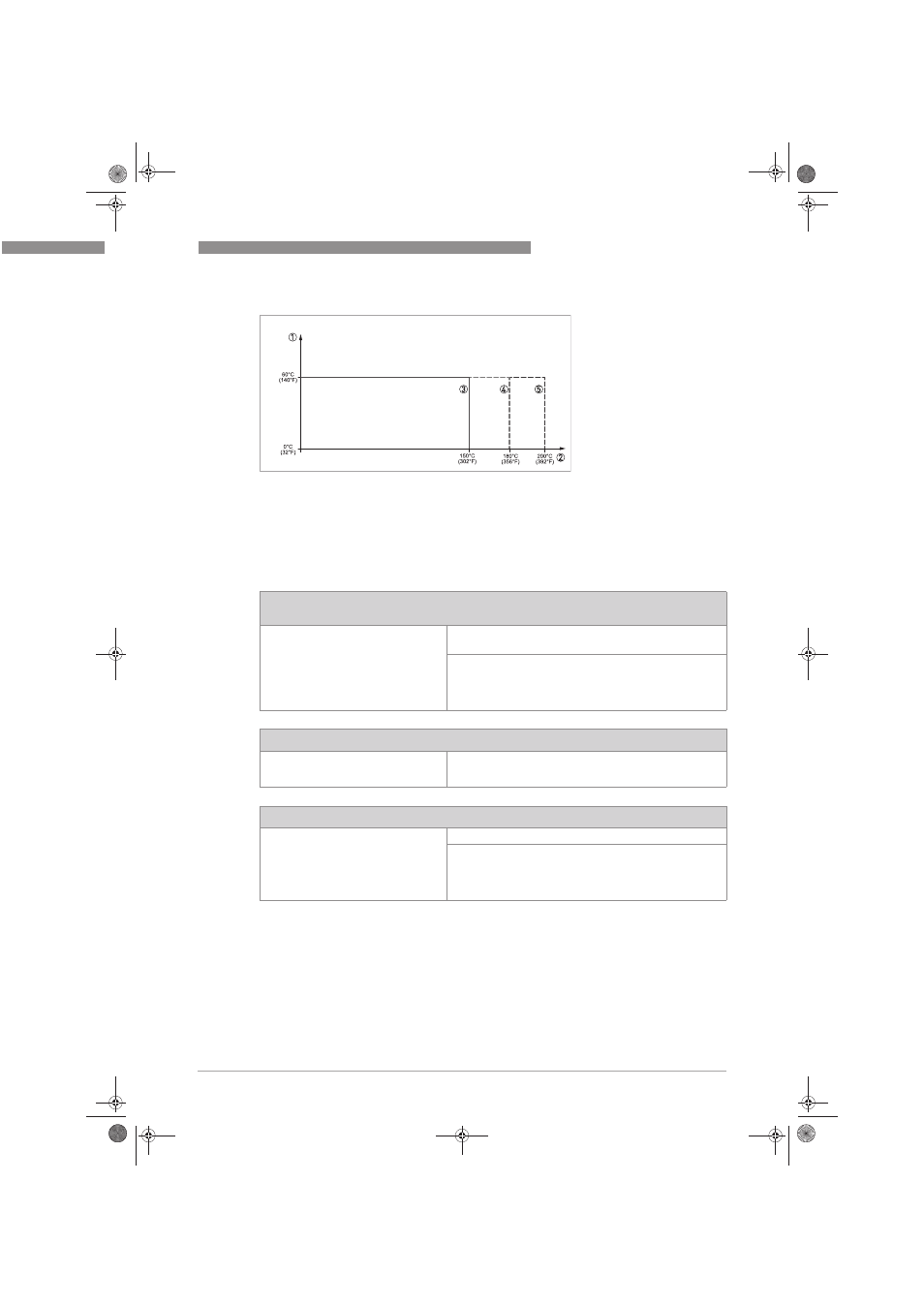
Figure 2-5: Temperature derating
1 Ambient temperature housing
2 Process temperature
3 Process temperature max. 150°C / 302°F
4 Process temperature max. 180°C / 356°F
5 Process temperature max. 200°C / 393°F
OPTIBAR * 5060 VGK5/6/D*A/W E/Z/6/7 with integrated electronics Z (4…20°mA),
H°(4…20°mA/HART) or A (4…20°mA/HART with SIL qualification)
Supply and signal circuit:
(Terminals 1[+], 2[-]
Indicating and adjustment circuits:
(terminals 5, 6, 7, 8)
•
U
i
= 9.6...35 VDC
•
U
m
= 253 VAC
For connection to the circuit of the appropriate external
display unit in protection type flameproof enclosure "d" or for
connection of an OPTIBAR * 5060 in protection type
flameproof enclosure "Ex d ia" with integrated electronics S
or T as differential pressure measurement.
OPTIBAR * 5060 VGK5/6/D*A/W E/Z/6/7 with electronics S or T
Supply and signal circuit:
(Terminals 5,6,7,8 in electronics
compartment)
For connection of an
OPTIBAR * 5060 VGK5/6/D*A/W E with integrated electronics
H, A for differential pressure measurement
OPTIBAR * 5060 VGK5/6/D*A/W E/Z/6/7 version with separate cable outlet
Circuit between sensor unit and
external electronics (terminal 1 - yellow,
terminal 2 - white, terminal 3 - red,
terminal 4 - black)
in protection type intrinsic safety Ex ia IIC
For the OPTIBAR * 5060 VGK5/6/D*A/W E in the version with
the permanently mounted cable to the measuring sensor unit
and external electronics, the length of the supplied cable
between the external housing and the measuring sensor unit
should not exceed 180 m.
.book Page 11 Monday, July 7, 2014 3:31 PM