2 adjustment elements – KROHNE OPTISWITCH 3000C 2wire EN User Manual
Page 17
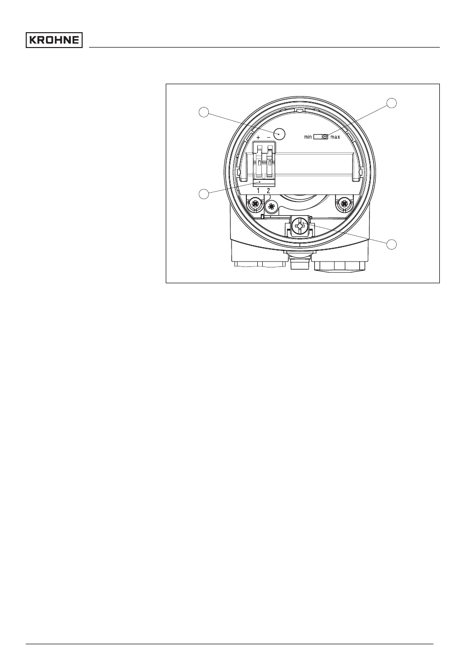
6.2 Adjustment elements
4
1
2
3
Fig. 10: Electronics module - Two-wire output
1
DIL switch for mode adjustment
2
Ground terminal
3
Screwed terminals
4
Control lamp
With the mode adjustment (min./max.) you can determine the
output current.
When using a signal conditioning instrument, always set the
mode switch to max. mode.
In this case, you select the requested mode acc. to the
"Function chart" (max. - max. detection or overfill protection,
min. - min.detection or dry run detection) on the signal
conditioning instrument.
When used on a control system, the following values apply:
l
Mode min.
- Vibrating element uncovered - 16 mA ±1 mA
-
Vibrating element covered - 8 mA ±1 mA
l
Mode max.
- Vibrating element uncovered - 8 mA ±1 mA
-
Vibrating element covered - 16 mA ±1 mA
Control lamp for indication of the switching condition.
l
green = 8 mA
l
red = 16 mA
l
red (flashing) = Failure (<2.3 mA)
Mode adjustment (1)
Signal lamp (4)
OPTISWITCH 3000 C - with two-wire output
17
Set up
30061
-EN
-060830
- BATCHFLUX 5500 C Quickstart EN (20 pages)
- IFC 050 Converter Quickstart EN (28 pages)
- IFC 100 Converter Quickstart EN (32 pages)
- IFC 300 Converter Quickstart EN (68 pages)
- OPTIFLUX 1000 Quickstart EN (20 pages)
- OPTIFLUX 2000 Quickstart EN (24 pages)
- OPTIFLUX 4000 Quickstart EN (24 pages)
- OPTIFLUX 4040C Quickstart EN (16 pages)
- OPTIFLUX 5000 Flange Quickstart EN (20 pages)
- OPTIFLUX 5000 Sandwich Quickstart EN (20 pages)
- OPTIFLUX 6000 Quickstart EN (28 pages)
- OPTIFLUX 7300 Quickstart EN (24 pages)
- OPTIPROBE Quickstart EN (16 pages)
- TIDALFLUX 2300 F EN (44 pages)
- TIDALFLUX 2300 F Quickstart EN (24 pages)
- WATERFLUX 3000 EN (40 pages)
- WATERFLUX 3000 Quickstart EN (24 pages)
- WATERFLUX 3070 EN (80 pages)
- WATERFLUX 3070 Quickstart EN (32 pages)
- USB ADAPTER PLUS EMF EN (16 pages)
- IFC 050 Converter Modbus EN (20 pages)
- IFC 100 Converter FOUNDATION FIELDBUS EN (64 pages)
- IFC 100 Converter Modbus EN (20 pages)
- IFC 300 Converter FOUNDATION FIELDBUS EN (60 pages)
- IFC 300 Converter HART 0102 EN (20 pages)
- IFC 300 Converter HART 0201 EN (23 pages)
- IFC 300 Converter Modbus EN (24 pages)
- IFC 300 Converter PROFIBUS PA DP EN (40 pages)
- OPTIFLUX 2000-4000 IECEx EN (16 pages)
- OPTIFLUX 2000-4000-5000-6000-7300-IFC 300 Ex EN (40 pages)
- OPTIFLUX 2000-4000-5000-6000 -IFC 100 Ex EN (24 pages)
- OPTIFLUX 4040 C Ex EN (20 pages)
- OPTIFLUX x300 Ex Zone2 EN (1 page)
- H250 M9 ES EN (36 pages)
- VA 40-VA 45 EN (36 pages)
- H250 M10 ATEX II2G Ex d EN (16 pages)
- H250 M10 ATEX II3D Ex t EN (16 pages)
- H250 M40 ATEX II2D Ex t-II2G Ex d EN (20 pages)
- H250 M40 ATEX II2G Ex i EN (20 pages)
- H250 M40 ATEX II3G Ex nA EN (20 pages)
- H250 M40 Ex II2G Reed EN (2 pages)
- H250 M9 ATEX II2G Ex i EN (16 pages)
- H250 M9S ATEX II3D Ex t-II3G Ex nA EN (20 pages)
- M8E Converter HART 0101 EN (13 pages)
- DK 32-DK 34 ATEX II2G Ex i EN (16 pages)