0 sensor alignment – KROHNE UFM 800 EN User Manual
Page 5
Installation and operating instructions UFM 800 W / UFM 800 C
5
12/2000
3.0
Mounting of the sensor supports and the square pipe
●
Mark the centers of places where the sensors must be fixed on the tubes (Drawing 1/2 SB/DB).
●
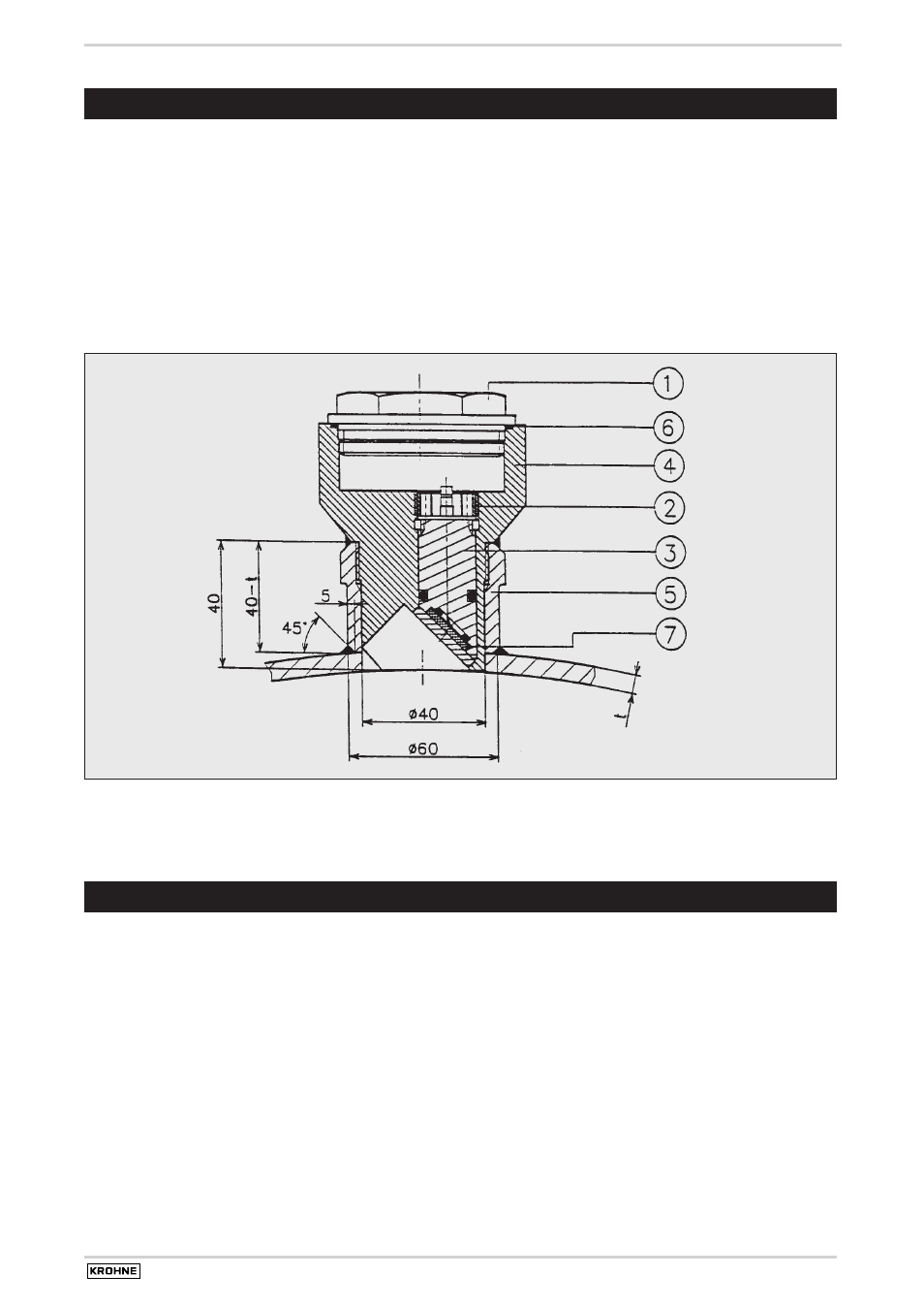
Drill holes at these places of diameter 40 mm (Drawing 3)
●
Machine the sensor supports so that they have the right curve for the pipe (outside diameter) and the right length (Drawing 3). Weld the
sensor supports on the pipe perpendicular to the pipe wall and around the holes, so that the end of the supports is situated at 40 mm from
the internal side of the pipe wall. Due to the welding, the thread of the sensor support can be deformed, by using a thread tap of 42 x 1.5
this can be solved.
●
Grind the interior of the pipe and sensor supports to get rid of burrs. Take care not to damage the thread inside the sensor supports.
●
Weld the square pipe on the appropriate place on the pipe (Drawing 1/2). The square pipe must be welded all around to create a closed
atmosphere inside (environmental protection class IP 67/68).
Drawing 3: Sensor FS 500W. 1. Cover 2. Nut, 3. Pies guiding, 4. Sensorbody, 5. Sensor Support, 6. O-ring, 7. Piezo
4.0
Sensor alignment
The sensors of each acoustic path must be aligned to have an optimum acoustic signal transfer. The best way to obtain this is by fluid alignment,
where the pipe is filled with fluid and the sensor position is optimized by monitoring the acoustic signal transfer. When this is impossible, the
sensor can be aligned optically. For this method it is necessary to have access to the inside of the pipe. The end result is that the acoustic
windows are parallel and on the same axis. This is acceptable for the acoustic signal transfer.
For single beam (SB) installations there is only one ultrasonic path and two sensors (Drawing 1). This path is named path 1 and it is composed
of sensors 1 and 2. For double beam (DB) installations there are two acoustic paths and four sensors (Drawing 2). The upper path is path 1,
composed of sensors 1 and 2. The lower path is path 2, composed of sensors 4 and 3. It is very important that both acoustic paths have the
same signal strength. This is only possible to optimize with fluid alignment, or with laser alignment.