Electrical connections, 5 connection examples – KROHNE OPTIFLUX 4040 C Ex EN User Manual
Page 13
ELECTRICAL CONNECTIONS
3
13
OPTIFLUX 4040 C
www.krohne.com
09/2010 - 7312232100 - AD EX OPTIFLUX 4040 C R01 en
3.5 Connection examples
In the following sections examples for connection of the OPTIFLUX 4040 C-EEx compact
flowmeter are described for operation in the 2-wire mode as well as in the 2x2-wire mode.
3.5.1 Example of OPTIFLUX 4040 C-EEx in 2-wire mode
The diagram shows an OPTIFLUX 4040 C-EEx with the terminal compartment in version A
(EEx de [ib] with U
m
= 60 V). The flowmeter is connected through a transmitter power supply
("EEx i" approved) in 2-wire mode. If data communication with the flowmeter through the HART
®
protocol is required, the transmitter power supply unit must be HART compatible. Terminals I,
I
gnd
are not polarity sensitive.
The entity parameters of the "EEx i" approved transmitter power supply, including the cable
capacitances and inductances, must fit the entity parameters of the OPTIFLUX 4040 C-EEx
compact flowmeter, namely U
i
= 30 V, I
i
= 100 mA, C
i
= 200 nF, L
i
= 0. Suitable HART
®
compatible
transmitter power supplies that can be used in combination of the OPTIFLUX 4040 C-EEx are:
• Phoenix PI/Ex-ME-RPSS-I/I
• CEAG 6/420
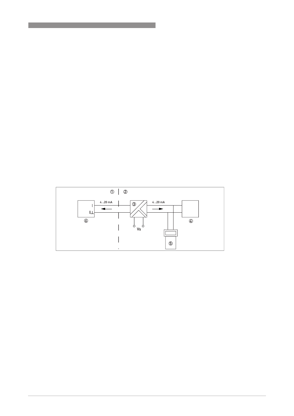
Figure 3-2: Connection example in 2-wire mode
1 Hazardous area
2 Safe area
3 Transmitter power supply (EEx i)
4 Process / display unit
5 Hand held terminal
6 OPTIFLUX 4040 C-EEx