Caution – HT instruments HT322 User Manual
Page 11
HT321 - HT322
EN - 10
4.3.4. Diode test and Continuity test
CAUTION
Before taking resistance measurements in circuit remove power from the
circuit being tested and discharge all capacitors.
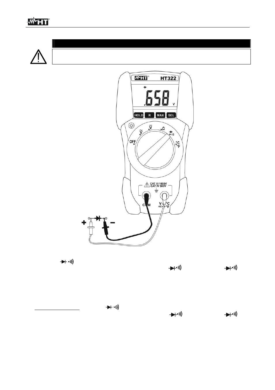
Fig. 5: Using the instrument for Diode test
1. Switch on /
2. Insert the test leads into the jack, the red plug into V
(for HT321) / V
°C°F
(for HT322) jack, and black plug into COM jack (see Fig. 5)
3. Connect the test leads to the diode under test observing the proper polarities indicated in
Fig. 5. The threshold voltage value expressed in mV under this situation is displayed
4. If the message "O.L" is displayed the diode terminals are reversed, the diode P-N
junction is damaged
5. For Continuity test switch on
/
then push “SEL” button
6. Insert the test leads into the jack, the red plug into V
(for HT321) /
V
°C°F
(for HT322) jack and black plug into COM jack
7. Connect the test leads to the circuit under test (see Fig. 4)
8. The resistance value is displayed and the instrument emits a sound signal if the
resistance value is <120
9. The message "
O.L.
" on the display indicates that the resistance value is higher than
2k