Detcon 412B-FB User Manual
Page 8
8. If applicable, connect a normally open momentary remote mounted switch to the terminal strip labeled “Alarm Reset”.
1.7 S
TART
U
P
Upon completion of all field wiring: Depress the power switch located on the front panel. Note that each Model
12B controller digital display illuminates. Varying readings may occur during sensor warm-up. A 10 second alarm
delay will occur on power up. Refer to section 3.0 for additional sensor start-up detail.
1.8 M
AINTENANCE
& R
EPAIR
The Detcon Model 412B-FB’s modular design allows for minimum down time during maintenance and/or repair.
The model 12B control modules may be changed by simply loosening its mounting screw and sliding the module
out of its card cage. See section 3.0 for more information on the 12B control module.
Replacement of the power switch, fuse holder, or alarm disable switch is accomplished by: removing the 10 screws
that secure the 412B-FB face plate; disconnecting the three plugs from their respective headers; remove the wires
from the plug of the component to be replaced; snap the component out of the 412B-FB face plate and then
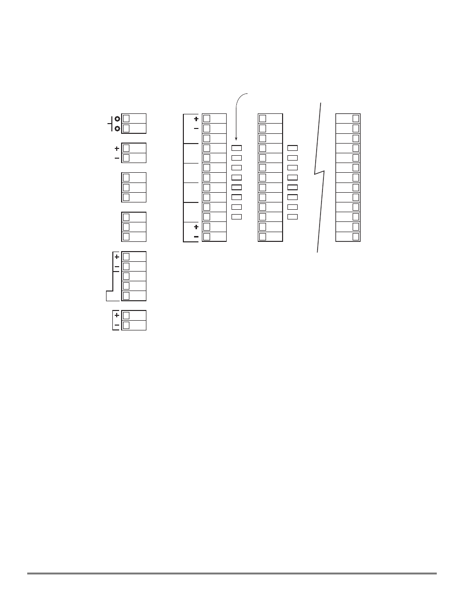
reassembly with the new component. Reference figure 2 for wiring details.
Replacement of the power supply is accomplished by: removing the 10 screws that secure the 1212F-FB face plate;
disconnecting the three plugs from their respective headers; disconnect the two power supply plugs from their
respective headers; remove the three screws that hold the power supply bracket the PCB motherboard; remove the
four screws that hold the power supply bracket to the power supply; disconnect the wires from the power supply
and then reassembly with the new power supply. Reference figure 2 for wiring details.
Model 412B-FB NEMA 4 Control Enclosure PG.8
RS-485
Alm Pwr
Alm Reset
VDC IN
VAC IN
L1
N
GND
N
GND
Alm Coil Pwr
VDC
VDC
VA
C
Zone Programming Jumpers
CH1
CH2
CH4
L1
A (+)
B (–)
Shld
mA
Sensor
NO/NC
Com
Alm 3
NO/NC
Com
Alm 2
NO/NC
Com
Alm 1
NO/NC
Com
Fault
4-20mA
Out
Figure 6