Detcon 412B User Manual
Page 5
7. Based on the application and use of relay contact outputs, complete all wiring terminations prior to application
of power. Shut-in controls may be omitted until system test is complete. Terminals are labeled “ALARM 1”,
“ALARM 2”, “ALARM 3”, and “FAULT” (COM & NO/NC). Relay contact outputs may be discreet or zoned
via the gold-plated jumper tabs.
8. If applicable, terminate a remote mounted normally open momentary switch to the terminations labeled “Alarm
Reset”. Activation of the alarm reset function will reset the alarms of all Model 12B controllers. The reset func-
tion is effective when the Model 12B’s respective alarms have been programmed in the latching position and
alarm conditions have passed. Each Model 12B controller has its own alarm reset switch which is discussed fur-
ther in section 2.0.
Model 412B Rack Mount Control Enclosure PG.5
Alarm
Reset
L1
N
A (+)
B (–)
Shld
RS-485
VDC In
GND
V
AC In
Zone Programming Jumpers
mA
Sensor
NO/NC
Com
Alm 3
NO/NC
Com
Alm 2
NO/NC
Com
Alm 1
NO/NC
Com
Fault
4-20mA
Out
CH4
CH3
CH1
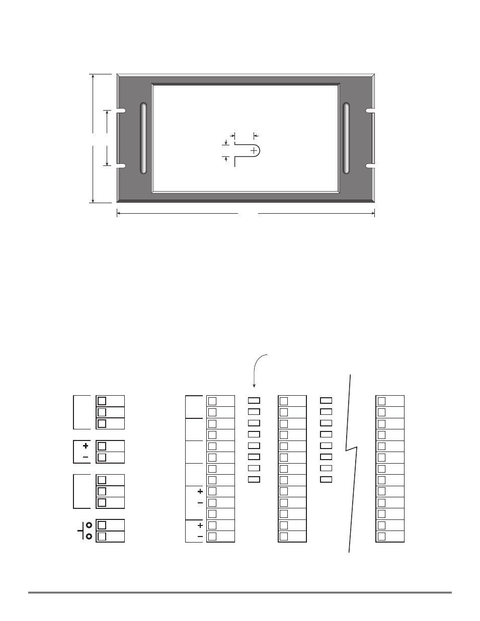
Figure 2
Panel cutout (centered) 12.5 x 6.65
Panel depth - 8.75
3
14
7
.218
.375
Slot Detail
use 10-32 screw
Figure 1