Detcon 1212B-FB User Manual
Page 7
1.6 I
NSTALLATION
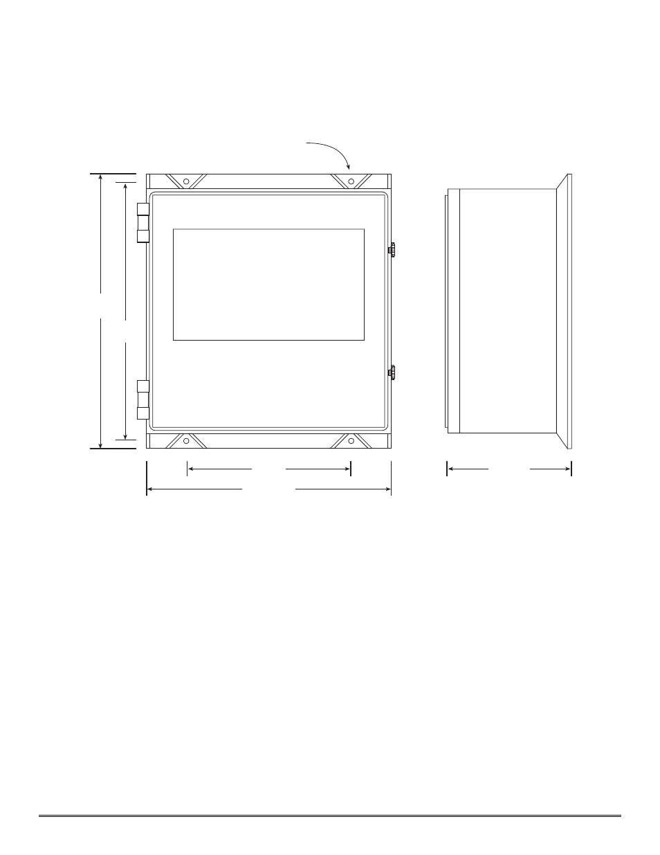
1. Securely mount the 1212B-FB enclosure in accordance with the drawing in figure 5.
N
No
ottee::
Reference figure 6 for wiring terminations.
C
Ca
au
uttiio
on
n::
Observe correct polarity when terminating all input/output field wiring. Failure to do so may result in
circuit damage on power up.
2. Connect 117VAC input to the terminal strip labeled “VAC IN” (L1, N, GND).
3. If applicable, connect a 24VDC source or standby battery to the terminal strip labeled “VDC IN” (+ and –).
4. Refer to installation and wiring detail of remote mount sensor assemblies as detailed in section 3.0. Terminate
field wiring from sensors to the 1212B-FB motherboard. Terminals are labeled “Sensor” (mA, + and –).
5. If applicable, terminate the discrete 4-20 mA outputs to external device(s). Terminals are labeled “4-20mA Out”
(+ and –).
6. If applicable, terminate the RS-485 serial output to external device(s). Terminals are labeled “RS-485” (A+, B–,
and Shield). RS-485 outputs may be common or zoned (up to two zones) via the gold-plated jumper tabs.
7. Based on the application and use of relay contact outputs, complete all wiring terminations prior to application
of power. Shut-in controls may be omitted until system test is complete. Terminals are labeled “ALARM 1”
(Com & NO/NC), “ALARM 2” (Com & NO/NC), “ALARM 3” (Com & NO/NC), and “Fault” (Com &
NO/NC). Relay contact outputs may be discrete or zoned via the gold-plated jumper tabs. Relay contact outputs
may be used in conjunction with the multiple alarm relay circuit as described in section 1.3.
Model 1212B-FB NEMA 4 Control Enclosure PG.7
23.07
14
20.63
Mounting Holes - 7/16" Dia.
10.25
21.81
Figure 5