2 start up, Flow fault circuit, Flow fault contacts – Detcon 972-04012-PLA User Manual
Page 4
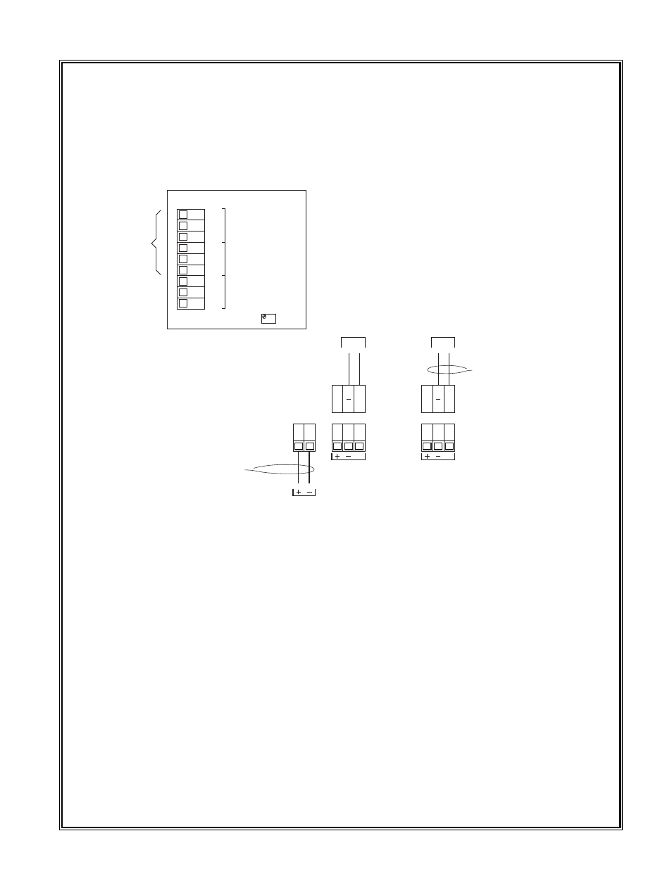
Caution: Observe correct polarity when terminating all input/output wiring. Failure to do so may result in
circuit damage on power up. Seethe field wiring diagram below for terminal locations.
4. Connect 12VDC to the connector labeled “VDC IN”.
5. If applicable, connect a remote recording device or computer to the 4-20 mA signal output connectors.
The terminals are labeled SENSOR “–” and “mA”.
7. If applicable, connect alarm devices. Discreet alarm relay contacts are provided for three alarms: Fault,
Low and High. The contacts consist of common and choice of normally open or normally closed. Contact
output selections are jumper programmable on the sensor connector board. See the sensor manual for con-
tact ratings and other information.
8. If applicable, connect flow fault alarm wiring. Two sets of form C contacts (common, normally open and
normally closed) are provided. Relay contacts are rated 1 amp at 30VDC/.24 amp at 125VDC.
1.2 START UP
Upon completion of all tubing connections and field wiring turn on the power switch located on the enclo-
sure door. Note that the power lamp illuminates. If applicable, note that the sensor LCD indicators activate.
Varying readings may occur during sensor warm-up. Allow approximately 1 hour to stabilize (24 hours is best).
Detcon Model 972-04012-PLA Gas Detection System PG.4
P7
P6
mA
12 VDC
IN
SENSOR #1
Flow
Fault
Circuit
COM
NO
NC
1
COM
NO
NC
2
COM
NO
NC
3
PT1
mA
4-20mA
Wire 12 VDC to the lugless
connectors.
Two discreet form C dry contacts are provided (2 & 3) by the
flow fault circuit for alarm devices. The first set of contacts
(1) are prewired to interrupt the 4-20mA signal output in the
event of a flow fault. This will allow for flow fault monitoring
at any controller/computer that the signal is wired in to.
P10
mA
SENSOR #2
mA
4-20mA
Wire th 4-20mA output signal to
the plug-type connnector
FLOW
FAULT
CONTACTS