Typical each channel, Alarm jumper tabs – Detcon 410-N1-24VDC User Manual
Page 3
1.3 R
EMOTE
R
ESET
The reset function is effective when the Model 10B's respective alarms have been programmed in the latching
position and alarm conditions have passed. The alarm reset function is common to all controllers and is acti-
vated by closing the circuit between the two reset contacts. A normally open momentary switch is suitable.
1.4 I
NSTALLATION
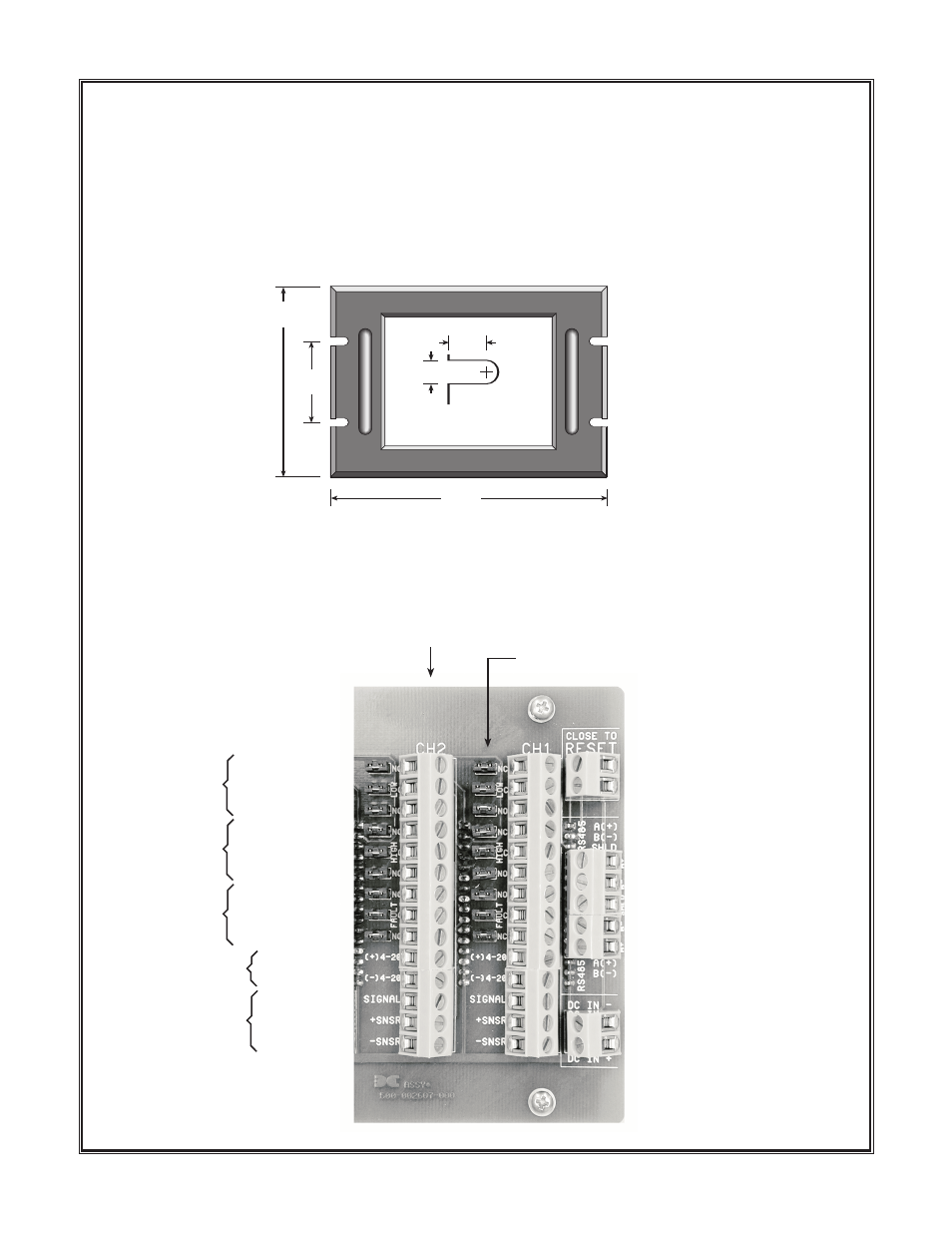
1. Securely mount the 410-N1-24VDC rack enclosure in accordance with Figure 1.
N
No
otte
e:: Reference f igure 2 for wiring terminations
C
Ca
au
uttiio
on
n:: Observe correct polarity when terminating all input/output f ield wiring. Failure to do so may
result in circuit damage on power up.
Detcon Model 410-N1-24VDC Rack Panel Mount Control Enclosure PG.3
Fig. 1
.218
.375
Slot Detail
use 10-32 screw
Panel cutout
(centered) 5.75" x 5"
Panel depth - 8"
2.25
7
5.25
Typical Each Channel
Normally Closed
Common
Normally Open
Normally Closed
Common
Normally Open
Normally Open
Common
Normally Closed
+
Common
+ Signal (mA)
+
–
External Reset
Close to Reset
DC In Common
DC In Positive
Sensor
Aux. RS-485 A(+)
Aux. RS-485 B(–)
RS-485 B(–)
Shield
RS-485 A(+)
Low Alarm
High Alarm
Fault Alarm
4-20 mA Output
Alarm Jumper Tabs
Fig. 2