Control terminals, Figure 2 – Detcon 612B User Manual
Page 5
1.5 S
TART
U
P
Upon completion of all field wiring apply 24VDC power. Note that each Model 12B controller’s digital display illu-
minates. Varying readings may occur during sensor warm-up. A 10 second alarm delay will occur on power up.
Refer to sections 2.0 and 3.0 for additional start-up detail.
1.6 S
PARE
P
ARTS
L
IST
0224
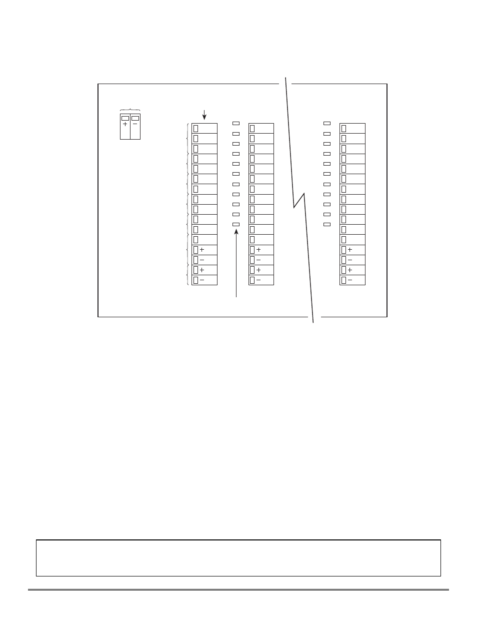
Gold plated jumper tab
1.7 W
ARRANTY
Detcon Inc., as manufacturer, warrants under intended normal use each new Model 612B rack mount control
enclosure to be free from defects in material and workmanship for a period of one year. The warranty period begins
from the date of shipment to the original purchaser and ends one year thereafter. All warranties and service policies
are FOB the Detcon Inc. facility located in The Woodlands, Texas.
Model 612B Rack Mount Control Enclosure PG.5
4-20 mA Output
Typical
Each Channel
24 VDC In
COM
NO/NC
COM
NO/NC
COM
NO/NC
COM
NO/NC
mA
Fault Alarm
High Alarm
Low Alarm
HI-HI Alarm
S
B
A
Sensor
RS-485
COM
NO/NC
COM
NO/NC
COM
NO/NC
COM
NO/NC
mA
S
B
A
Zone Programming Jumpers
COM
NO/NC
COM
NO/NC
COM
NO/NC
COM
NO/NC
mA
S
B
A
Channel 1
Channel 5
Channel 6
Control Terminals
Figure 2
Shipping Address: 3200 A-1 Research Forest Dr., The Woodlands, Texas 7381
Mailing Address: P.O. Box 8067, The Woodlands, Texas 77387-8067
phone 888-367-4286, 281-367-4100 • fax 281-292-2860 • www.detcon.com • [email protected]