Detcon 1212B User Manual
Page 4
1.4 I
NSTALLATION
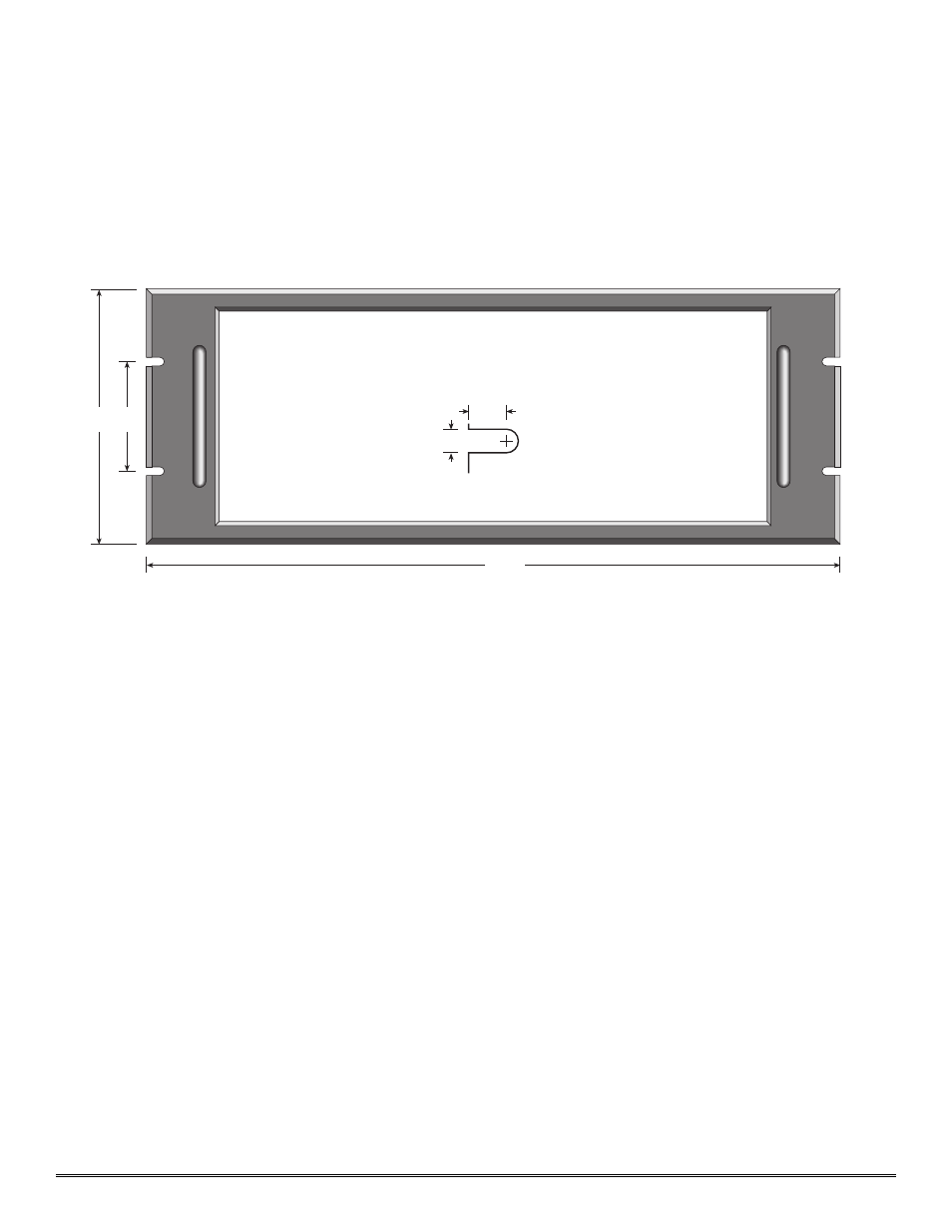
1. Securely mount the 1212B enclosure in accordance with the drawing in figure 1.
N
No
ottee::
Reference figure 2 for wiring terminations.
2. Connect 24VDC input to the terminal strip labeled “VDC IN” (+ and —).
3. Refer to installation and wiring detail of remote mount sensor assemblies as detailed in section 3.0. Terminate
field wiring from sensors to the 1212B motherboard. Terminals are labeled “SENSOR” (MA, + and —).
4. If applicable, terminate the discrete 4-20 mA output to external device(s). Terminals are labeled “4-20 mA OUT”
(+ and —).
5. If applicable, terminate the RS-485 serial output to external device(s). Terminals are labeled “RS-485” (A+, B–,
and Shield). RS-485 outputs may be common or zoned (max two zones) via the gold-plated jumper tabs.
6. Based on the application and use of relay contact outputs, complete all wiring terminations prior to application
of power. Shut-in controls may be omitted until system test is complete. Terminals are labeled “ALARM 1”,
“ALARM 2”, “ALARM 3”, and “FAULT” (COM & NO/NC). Relay contact outputs may be discreet or zoned
via the gold-plated jumper tabs.
7. If applicable, terminate a remote mounted normally open momentary switch to the terminations labeled “Alarm
Reset”. Activation of the alarm reset function will reset the alarms of all Model 12B controllers. The reset func-
tion is effective when the Model 12B’s respective alarms have been programmed in the latching position and
alarm conditions have passed. Each Model 12B controller has its own alarm reset switch which is discussed fur-
ther in section 2.0.
Model 1212B Rack Mount Control Enclosure PG.4
Panel cutout (centered) 17.5 x 6.65
Panel depth - 8.75
3
19
7
.218
.375
Slot Detail
use 10-32 screw
Figure 1