Detcon TP-624C User Manual
Page 4
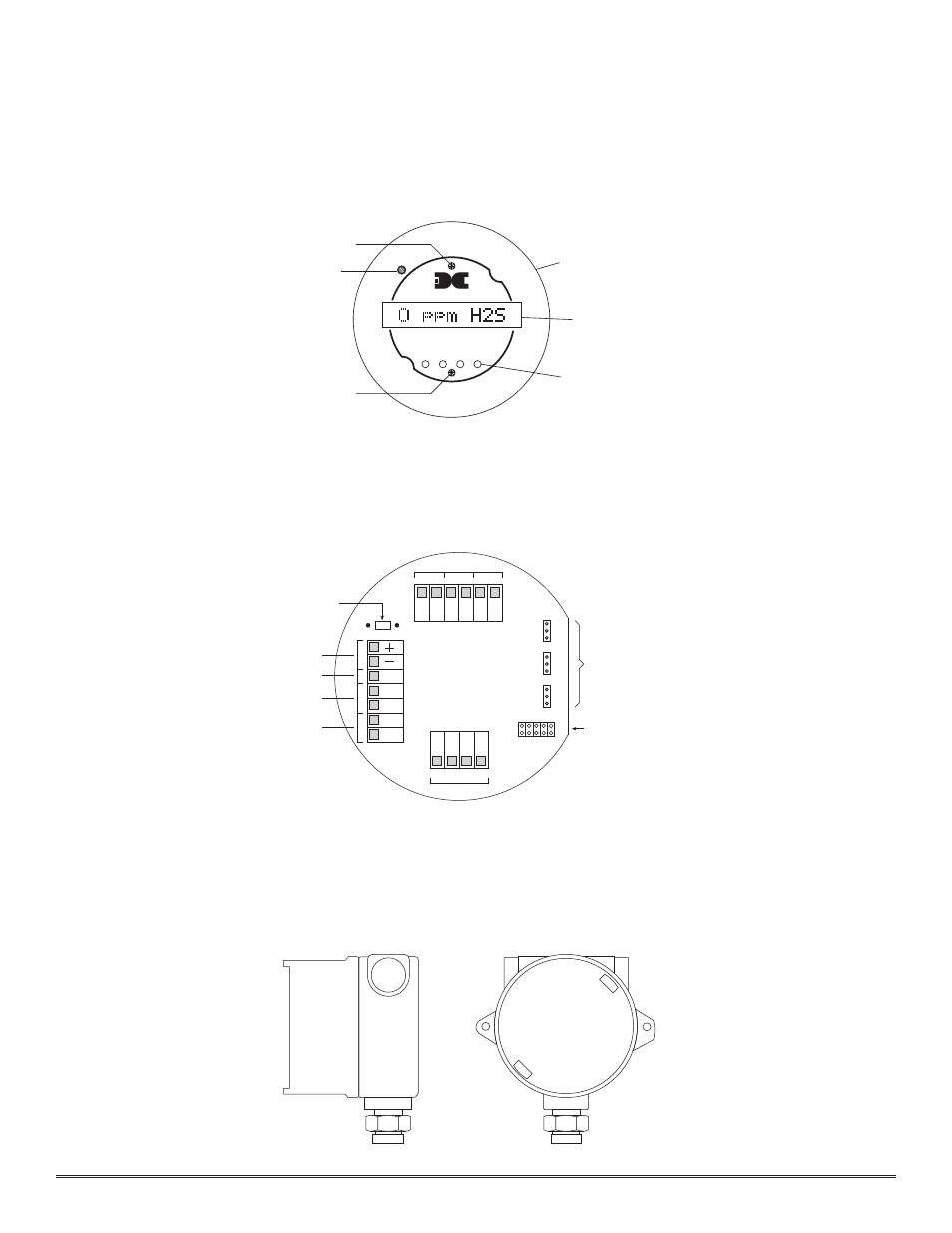
3.0.2 Microprocessor Control Circuit
The control circuit is microprocessor based and is packaged as a plug-in f ield replaceable module, facilitating easy
replacement and minimum down time. Circuit functions include a basic sensor pre-amplif ier, on-board power sup-
plies, microprocessor, back lit alpha numeric display, alarm status LED indicators, magnetic programming switches,
an RS-485 communication port, and a linear 4-20 mA DC output.
3.0.3 Base Connector Board
The base connector board is mounted in the explosion proof enclosure and includes: the mating connector for the
control circuit, reverse input and secondary transient suppression, input f ilter, alarm relays, lugless terminals for all
f ield wiring, and a terminal strip for storing unused programming jumper tabs. The alarm relays are contact rated 5
amps @ 125 VAC, 5 amps @ 30 VDC and coil rated at 24 VDC. Gold plated program jumpers are used to select
either the normally open or normally closed relay contacts.
3.0.4 Explosion Proof Enclosure
The sensors are packaged in a cast metal explosion proof enclosure. The enclosure is f itted with a threaded cover
that has a glass lens window. Magnetic program switches located behind the transmitter module face plate are acti-
vated through the lens window via a hand-held magnetic programming tool allowing non-intrusive operator inter-
face with the sensor. All calibration and alarm level adjustments can be accomplished without removing the cover
or declassifying the area. Electrical classif ication is Class I; Division 1; Groups B, C, D (explosion proof).
Detcon Model TP-624C Hydrogen Sulfide Sensor PG.4
detcon inc.
Program Switch #2
FLT
ALM
1
CAL
MicroSafe™ H2S Gas Sensor
HOUSTON, TEXAS
PGM
2
PGM
1
ALM
2
MODEL
TP-624C
CONTRAST
Alarm & Cal LEDs
Program Switch #1
Menu Driven Display
Display Contrast Adjust
Plug-in Microprocessor Control Circuit
NC
ALARM 1
W
H
T
B
L
K
Y
E
L
B
LU
MA
VDC Power In
NO
NC
NO
NC
NO
N
O
/N
C
C
O
M
N
O
/N
C
C
O
M
N
O
/N
C
C
O
M
FAULT
ALM-2
ALM-1
Alarm Dry Contacts
ALARM 2
FAULT
R1
A
B
A
B
4-20 mA Output
RS-485 In
RS-485 Out
Optional Voltage
Developing Resistor
Use 250 ohm 1/4w
JUMPERS
UN-USED
Jumper Programmable Alarm Outputs
Normally Open or Normally Closed
Sensor
Place un-used alarm programming
jumper tabs here