Iii. installation – Asus P/I-XP6NP5 User Manual
Page 15
ASUS P/I-XP6NP5 User’s Manual
9
III. INSTALLATION
III. INST
ALLA
TION
(Jumpers)
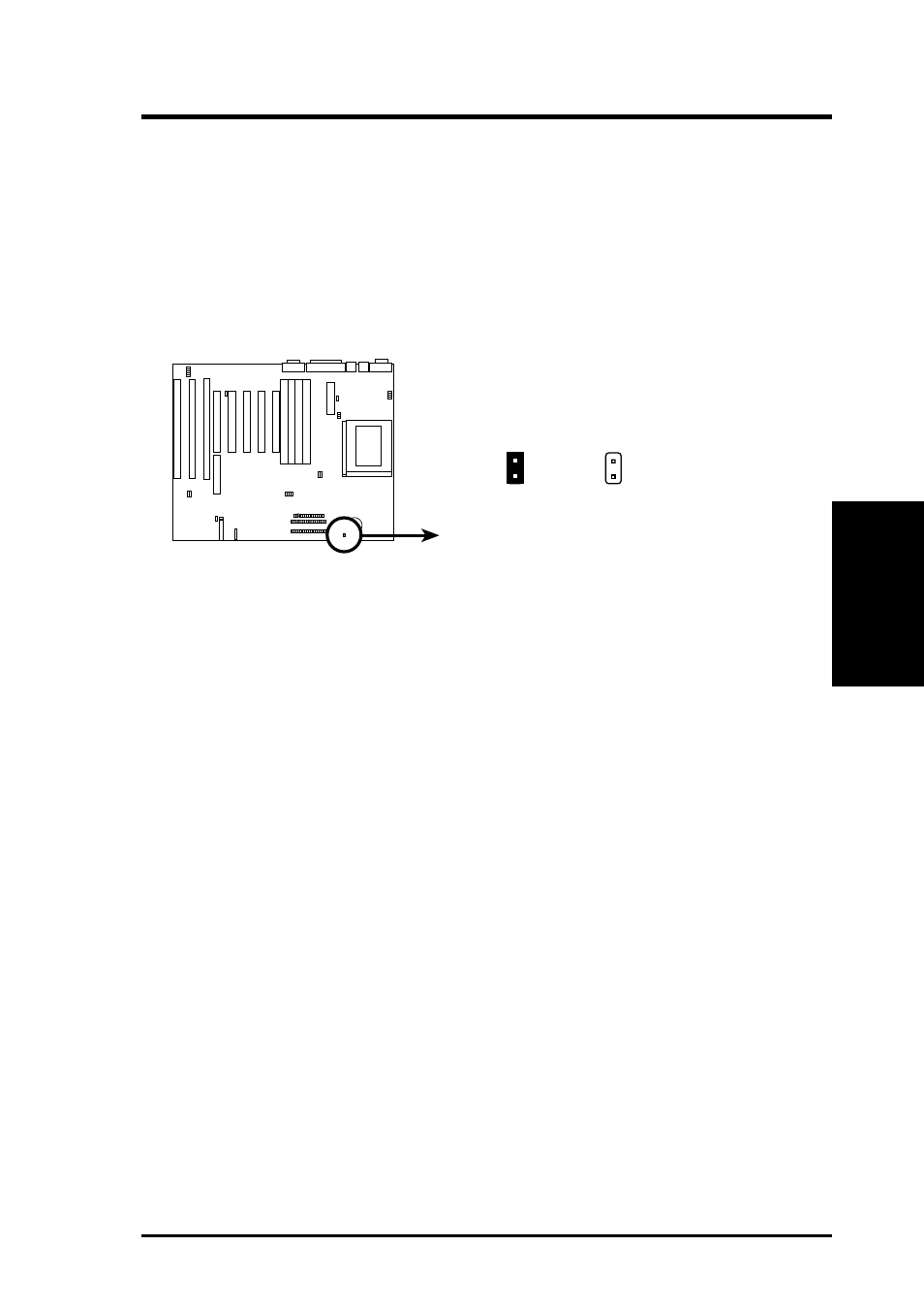
4. Battery Test Lead (JP7)
The Real Time Clock RAM is powered by the onboard button cell battery. You
can test the battery’s current by removing this jumper and attaching a current
meter to each pin. WARNING: You must unplug the power cord to your
power supply to ensure that there is no power to your motherboard. The
RTC RAM containing BIOS setup information will be cleared by this ac-
tion. You must enter BIOS to “Load Setup Defaults” and re-enter any user
information after removing and reapplying this jumper.
JP7
Battery Test Lead
Operation
Test Mode
JP7
See also other documents in the category Asus Hardware:
- Xonar DX (80 pages)
- Xonar DX (10 pages)
- PCI Express Audio Card Xonar DX (70 pages)
- Audio Card Xonar D2X (70 pages)
- Xonar D2X (88 pages)
- Xonar D2X (84 pages)
- D2X (88 pages)
- ROG Xonar Phoebus (72 pages)
- ROG Xonar Phoebus (122 pages)
- Xonar DSX (26 pages)
- Xonar DSX (29 pages)
- Xonar DGX (38 pages)
- Xonar DGX (33 pages)
- Xonar DGX (58 pages)
- Xonar DG (54 pages)
- Xonar DG (58 pages)
- Xonar DG (32 pages)
- Xonar DG (28 pages)
- Xonar Essence ST (35 pages)
- Xonar Essence ST (40 pages)
- Xonar Essence ST (53 pages)
- Xonar Essence ST (52 pages)
- Xonar DS (54 pages)
- Xonar DS (33 pages)
- Xonar Xense (70 pages)
- Xonar Xense (45 pages)
- Xonar Xense (47 pages)
- Xonar U3 (56 pages)
- Xonar U3 (38 pages)
- Xonar Essence STX (49 pages)
- Xonar Essence STX (10 pages)
- Xonar Essence STX (32 pages)
- XONAR D1 E4009 (72 pages)
- Xonar D1 (72 pages)
- Xonar D1 (80 pages)
- Xonar D1 (10 pages)
- Xonar Essence One (7 pages)
- Xonar Essence One (5 pages)
- Xonar HDAV 1.3 (100 pages)
- Motherboard M4A78-EM (64 pages)
- A7N8X-VM/400 (64 pages)
- K8V-XE (86 pages)
- K8V-XE (20 pages)
- M2R32-MVP (60 pages)
- M2R32-MVP (160 pages)