J6 — power, J7 — keyboard, Switch descriptions (s1 – s4) – Ampro Corporation LITTLE BOARD P5X User Manual
Page 16: Switch descriptions (s1 – s4) –10
1–10
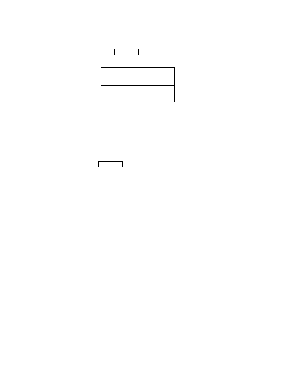
J6 — Power
If you connect J5 on the I/O board to J16 on the Little Board, you can use J6 to connect -5V and -
12V power supplies to the Little Board. Table 1– 2 shows J6 wiring.
J6 Pin
Signal
1
-12 Volts
3
-5 Volts
2, 4
Ground
Table 1– 2. J6 Power Wiring
J7 — Keyboard
If you connect J5 on the I/O board to J16 on the Little Board, you can use J7 to connect a PS/2
keyboard. J7 is a standard 5-pin DIN connector.
Switch Descriptions (S1 – S4)
There are four switches on the I/O Development Board. They are identified by silkscreen
designations S1, S2, S3, and S4. Table 1– 3 describes each switch function.
Switch
Name
Description
S1*
Lid
Power management input: causes an SMI to simulate a laptop lid
closure.
S2*
Pwr
Power management input (push-button switch): when pushed for 6
seconds, it powers down the board. When pressed again, the
board powers up.
S3*
Lo-Pwr
Power management input: causes an SMI to simulate a low-
battery condition.
S4
Reset
Standard Reset signal to the Little Board
* For information about implementing S1, S2, and S3 functionality, contact Ampro Technical
Support.