Assembly and adjustments (continued) – WEN 3912 10 inch band saw User Manual
Page 16
Assembly and adjustments (continued)
If a blade is being replaced with a new one of a different size, the adjustment described above
may fall out of range and further adjustment may be required as follows:
Loosen the hex cap screw (G, not visible) with a 10mm wrench and adjust the entire assembly
backwards or forwards to clear the back of the saw blade. Tighten screw (G), and then fine-tune
the adjustment by repeating the first part of this step.
6. Secure the roller guide (A) by tightening the thumbscrew (B, upper guide) or setscrew (B,
lower guide).
Guide Bearing Adjustment(Figure 10)
WARNING:Disconnect machine from the
power source! Never make adjustments with
the machine running! Failure to comply may
cause serious injury!
Disconnect machine from power source.
Note: Blade must already be tensioned and tracking
properly.
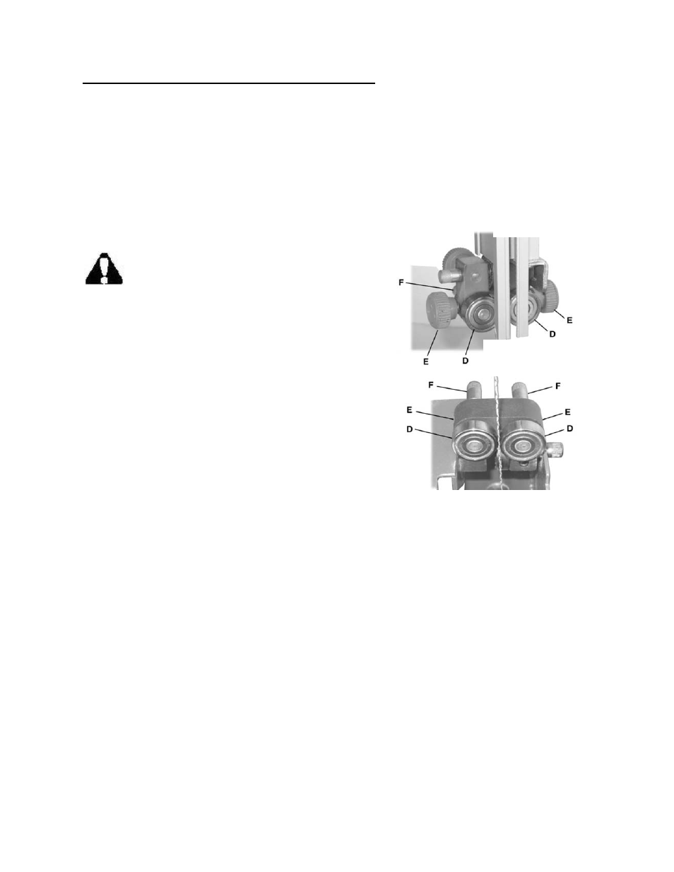
For the upper-blade guide, loosen two thumbscrews (E).
For the lower blade guide, loosen two setscrews (E) with
the 3mm hex wrench provided.
Slide the adjustment shaft (F) to position each roller
guide (D) approximately 1/16" behind the gullets of the
saw blade.
Figure 10
Upper blade guide
assembly
Lower blade guide assembly
The roller guide (D) is mounted on a concentric shaft (F). When the shaft is rotated, the relative
position of the guide to the blade can be changed.
Rotate each adjustment shaft (F) to position the guides (D) within 1/32" of the saw blade.
Secure the roller guides (D) by tightening thumbscrews (E, upper guide) or setscrews (E, lower
guide).
16